Three stage power source for electric ARC welding

a power source and electric arc technology, applied in the energy industry, efficient power electronics conversion, manufacturing tools, etc., can solve the problems of switching losses, higher current and voltage stresses, and higher switching speeds, so as to improve portability, high switching speeds, and control system the effect of band width

Active Publication Date: 2013-11-12
LINCOLN GLOBAL INC
View PDF194 Cites 60 Cited by
  • Summary
  • Abstract
  • Description
  • Claims
  • Application Information

AI Technical Summary

Benefits of technology

[0024]The primary object of the present invention is the provision of a novel three stage power source wherein the first stage has an active soft switching circuit for the fast switching power switch and the second stage is an unregulated inverter forming a part of an isolation stage, which inverter has a soft switching characteristic based upon a fixed high duty cycle for its several switches.
[0026]Yet another object of the present invention is the provision of a three stage power source, as defined above, which three stage power source also includes an output stage in the form of a chopper with the power switch of the chopper having a passive soft switching circuit.
[0027]Yet a further object of the present invention is the provision of a three stage power source, as defined above, which power source includes an active soft switching circuit for the first stage, an inherent soft switching characteristic for the second stage, and a passive soft switching circuit for the third stage.

Problems solved by technology

There is a downside to the use of such higher switching speeds.
Such switching speeds cause switching losses.
However, this type of prior soft switching control often causes higher current and voltage stresses because of the sinusoidal waveforms and still has conduction losses.
Furthermore, the soft switches input stage is combined with a second stage having an inherent soft switching capability using a fixed duty cycle, phase shift unregulated inverter.

Method used


Image

  • Three stage power source for electric ARC welding
  • Three stage power source for electric ARC welding
  • Three stage power source for electric ARC welding

Examples


Embodiment Construction

FIGS. 22-24

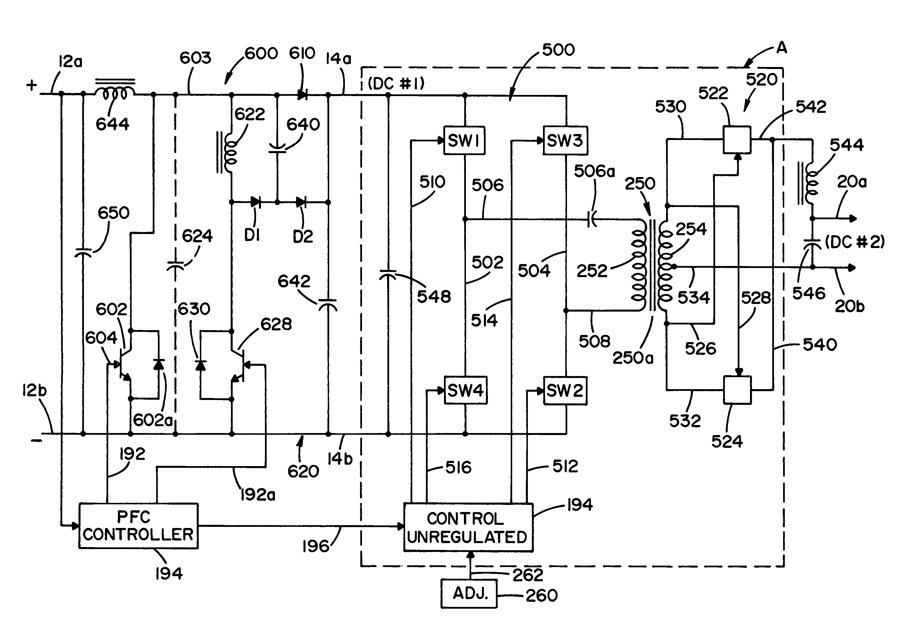
[0056]This description relates to FIGS. 22-27 and uses the numbers of those figures to indicate like components, while using some relevant numbers from FIGS. 1-17. The 600 numbers in FIGS. 18-21 are not used for the same components in FIGS. 22-27. In FIG. 22 the first two stages of the improved three stage power source includes unregulated converter A as best shown in FIG. 17 wherein the input DC signal across lines 14a, 14b is provided by a novel first input stage shown as boost converter 600 (FIG. 22) having power switch 602 (FIG. 22) switched by a gate signal in line 604 (FIG. 22). Switch 602 (FIG. 22) is turned on after auxiliary switch 628 is turned on. The timing of gating signals in lines 192 and 192a is by power factor correcting controller 194. A high frequency signal in line 192 causes a high frequency switching signal in gate 604 (FIG. 22) of main power switch 602 (FIG. 22) with anti-parallel diode 602a, in accordance with standard boost technology. The timing ...


PUM

PropertyMeasurementUnit
frequencyaaaaaaaaaa
frequencyaaaaaaaaaa
output voltageaaaaaaaaaa

Abstract

A three stage power source for an electric arc welding process comprising an input stage having an AC input and a first DC output signal; a second stage in the form of an unregulated DC to DC converter having an input connected to the first DC output signal, a network of switches switched at a high frequency with a given duty cycle to convert the input into a first internal AC signal, an isolation transformer with a primary winding driven by the first internal high frequency AC signal and a secondary winding for creating a second internal high frequency AC signal and a rectifier to convert the second internal AC signal into a second DC output signal of the second stage, with a magnitude related to the duty cycle of the switches; and, a third stage to convert the second DC output signal to a welding output for welding wherein the input stage has a regulated DC to DC converter with a boost power switch having an active soft switching circuit.

Description

[0001]The invention relates to the field of electric arc welding and more particularly to an improved three stage power source for such welding and a novel relationship between the first two stages of the three stage power source.INCORPORATION BY REFERENCE AND BACKGROUND OF INVENTION[0002]Electric arc welding involves the passing of an AC or DC current between a metal electrode and a workpiece where the metal electrode is normally a cored metal wire or solid metal wire. A power source is used to create a given current pattern and / or polarity between the advancing electrode wire and workpiece so that the arc will melt the end of the advancing welding wire and deposit the molten metal on the workpiece. Although various converter technologies are used for power sources, the most effective is an inverter based power source where a switching network includes switches operated at high frequency to create the desired waveform or current level for the welding process. An inverter type power...

Claims


Application Information

Patent Timeline
Patent Type & Authority Patents(United States)
IPC IPC(8): B23K9/00
CPCB23K9/095B23K9/1043H02M1/4225H02M3/158H02M2001/007Y02B70/1425H02M7/487Y02B70/10Y02P70/10Y02P80/10H02M1/0006H02M1/342H02M1/007H02M1/0085B23K9/09B23K9/10
Inventor KOOKEN, TODD E.LUO, LIFENG
Owner LINCOLN GLOBAL INC
Why Eureka
Try Eureka