Quench protection circuit for superconducting magnet coils

a superconducting magnet and protection circuit technology, applied in the direction of superconducting magnets/coils, superconducting devices, magnetic bodies, etc., can solve the problems of arcing damage to components as well as the magnet, increase temperature, and overheating of the superconducting coil or voltage spik

Active Publication Date: 2013-11-12
GENERAL ELECTRIC CO
View PDF13 Cites 3 Cited by
  • Summary
  • Abstract
  • Description
  • Claims
  • Application Information

AI Technical Summary

Benefits of technology

[0008]In according to still another embodiment, a method for quenching superconducting coils includes coupling a quench protection circuit in parallel to at least one superconducting coil. The quench protection circuit comprises at least one quench heater assembly and at least one superconducting current limiter. A quench event is triggered by an increasing quench voltage across the at least one superconducting coil. The method further includes powering the quench heater upon said quench event and normalizing the at least one superconducting coil at heater regions, and turning the superconducting current limiter from a superconducting state to a normal state to increase the resistance of the quench protection circuit heater branch and limit the current of quench heater assembly to be less than its maximum allowable current.

Problems solved by technology

This is an irreversible action known as “quenching” or “quench”, which causes undesirable heat that can lead to increased temperature.
In addition, quench can lead to overheating within the superconducting coil or voltage spikes and arcing damage to components as well as the magnet.
Accordingly, there are electrical wires extending through the vacuum vessel, which requires additional cost and might adversely decrease vacuum reliability.

Method used


Image

  • Quench protection circuit for superconducting magnet coils
  • Quench protection circuit for superconducting magnet coils
  • Quench protection circuit for superconducting magnet coils

Examples


Embodiment Construction

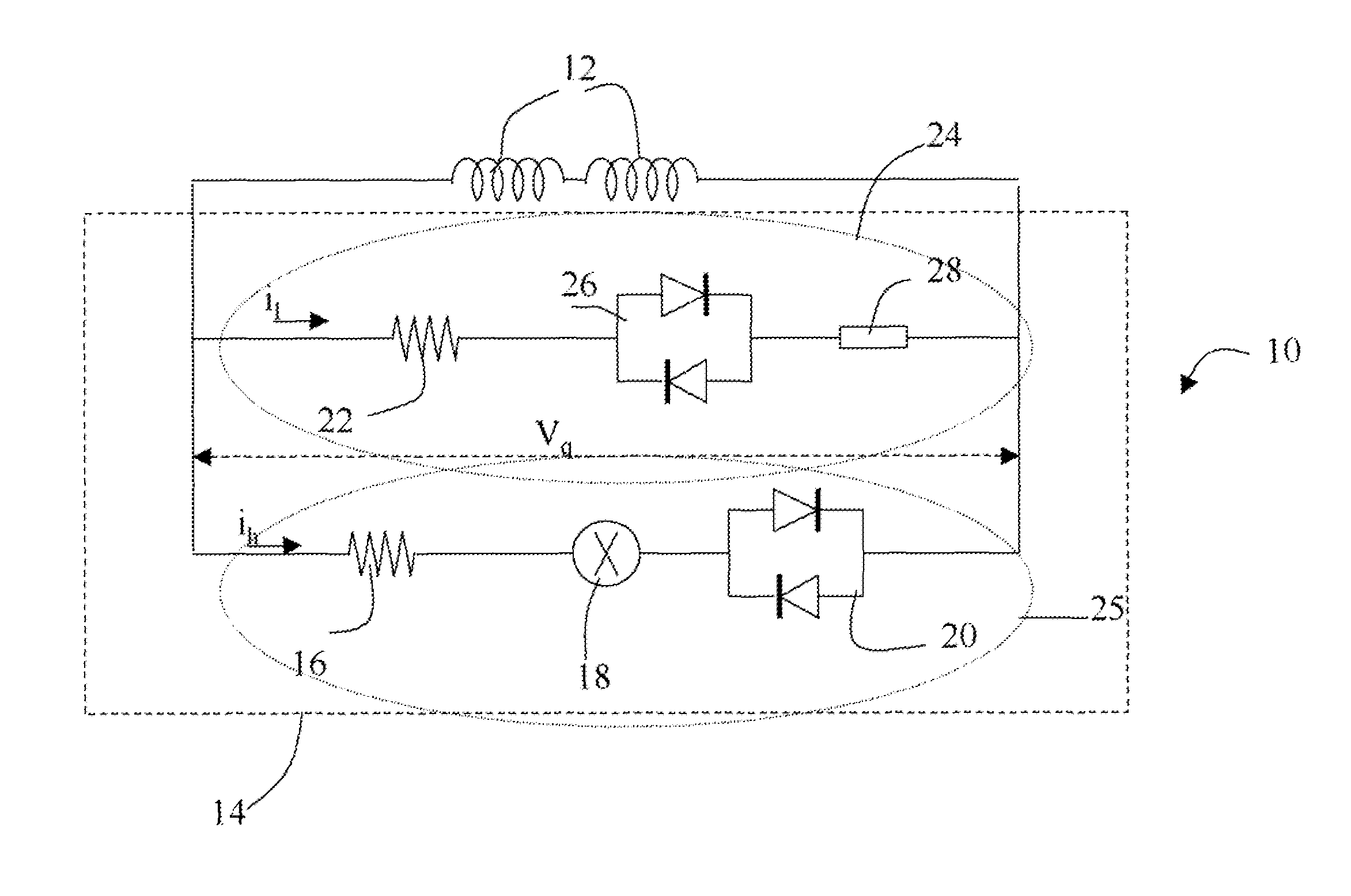
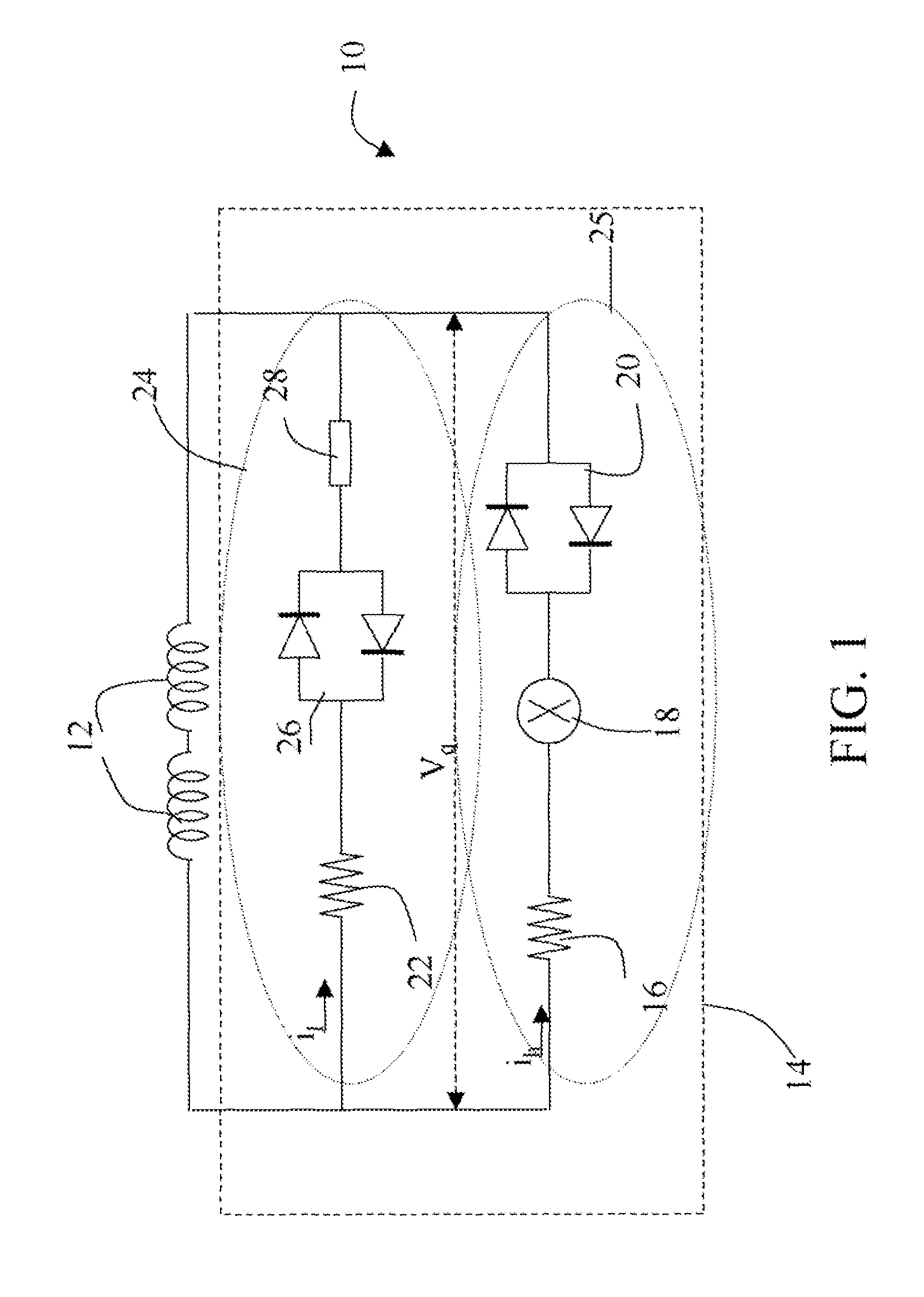
[0016]Embodiments of the disclosure relate to a superconducting magnet having a quench protection circuit. The quench protection circuit in one example comprises an electric quench heater assembly in thermal connection with a superconducting coil and a superconducting current limiter electrically connected in series with the quench heater assembly for limiting the electric current flowing through the quench heater assembly during a quench. The quench heater assembly and the superconducting current limiter are then in parallel connection with at least one superconducting coil. Once a quench event to the superconducting coil occurs, the increasing quench voltage across the superconducting coil powers the quench heater assembly, which then heats up and normalizes the superconducting coil at the quench heater regions, thereby spreading the energy and preventing damage to the superconducting magnet. As used herein “normalize” refer to that the superconductor of the coil is turned from a ...


PUM


Abstract

A superconducting magnet includes at least one superconducting coil and a quench protection circuit electrically coupled to said at least one coil in parallel. The circuit includes at least one quench heater assembly thermally coupled to the at least one coil, and at least one superconducting current limiter electrically connected in series with the at least one quench heater assembly. The superconducting current limiter has a superconducting state with zero resistance, and a normal state with a normal resistance to decrease an electric current flowing through the quench heater assembly.

Description

BACKGROUND[0001]Embodiments of the disclosure relate generally to superconducting magnets and more particularly relates to a quench protection circuit for superconducting coils of the superconducting magnets.[0002]In theory, superconducting magnets conduct electricity without resistance as long as the magnets are maintained at a suitably low temperature, which is referred to as “critical temperature” of the superconductor herein after. Accordingly, when a power source is initially connected to the superconducting magnet coils for a period to introduce a current flow through the magnet coils, the current will continue to flow through the coils after the superconducting switch is closed and power supply is disconnected because of the absence of electrical resistance in the coils, thereby maintaining a strong magnetic field in, for example, magnet resonance imaging (MRI) systems, and generators.[0003]Cooling systems are used for maintaining the superconducting magnets below the critica...

Claims


Application Information

Patent Timeline
Patent Type & Authority Patents(United States)
IPC IPC(8): G01R33/035
CPCH01F6/02H02H7/001Y02E40/69Y02E40/68H02H9/023Y02E40/60
Inventor WU, ANBOXU, MINFENGHUANG, XIANRUI
Owner GENERAL ELECTRIC CO
Why Eureka
Try Eureka