Cooling and exhaust system of dual electric oven

a dual-oven technology, applied in the field of dual-oven cooling and exhaust system, can solve the problems of assembly errors, increased complicated manufacturing process, etc., and achieve the effects of reducing productivity, increasing manufacturing time and cost, and complicating manufacturing process

Active Publication Date: 2013-11-19
LG ELECTRONICS INC
View PDF11 Cites 25 Cited by
  • Summary
  • Abstract
  • Description
  • Claims
  • Application Information

AI Technical Summary

Benefits of technology

[0013]In the above-described dual electric oven 2, the hot exhaust air A1 directed through the fan 144 of the upper oven 4 flows at a right side of the dual electric oven 2, the exhaust air A2 directed through the fan 174 of the lower oven 8 flows at a left side of the dual electric oven 2, and the cooling air B1 and the cooling air B2 flow at a middle portion of the dual electric oven 2. As such, the fan 144 of the upper oven 4, a motor (not shown) for operating the fan 144, the fan 174 of the lower oven 8, and a motor (not shown) for operating the fan 174 are respectively installed at different locations throughout the dual electric oven 2, which complicates the manufacturing process and could result in assembly errors. Further, the housing 5 and 7 respectively for the upper and lower ovens 4 and 8 may be separately manufactured, which increases the number of parts required to manufacture the dual electric oven 2, resulting in increased manufacturing time and cost, and hence decreased productivity.
[0015]It is an aspect of the present invention to provide a cooling and exhaust system of a dual electric oven having upper and lower ovens, in which an installation structure of a cooling fan and an exhaust structure provided for respectively cooling and exhausting the upper and lower ovens may be integrated into a simplified structure having common components to increase the manufacturing productivity, and fans provided in the upper and lower ovens may be independently controlled to operate at different speeds according to a desired operation to maximize the cooling efficiency.

Problems solved by technology

As such, the fan 144 of the upper oven 4, a motor (not shown) for operating the fan 144, the fan 174 of the lower oven 8, and a motor (not shown) for operating the fan 174 are respectively installed at different locations throughout the dual electric oven 2, which complicates the manufacturing process and could result in assembly errors.
Further, the housing 5 and 7 respectively for the upper and lower ovens 4 and 8 may be separately manufactured, which increases the number of parts required to manufacture the dual electric oven 2, resulting in increased manufacturing time and cost, and hence decreased productivity.

Method used


Image

  • Cooling and exhaust system of dual electric oven
  • Cooling and exhaust system of dual electric oven
  • Cooling and exhaust system of dual electric oven

Examples


Embodiment Construction

[0033]Reference will now be made in detail to the exemplary embodiments of the present invention, examples of which are illustrated in the accompanying drawings. The invention may, however, be embodied in many different forms and should not be construed as being limited to the embodiments set forth herein. Rather, these embodiments are provided so that this disclosure will be thorough and complete, and to convey the concept of the invention to those skilled in the art. Wherever possible, the same reference numerals will be used throughout the drawings to refer to the same or like parts.

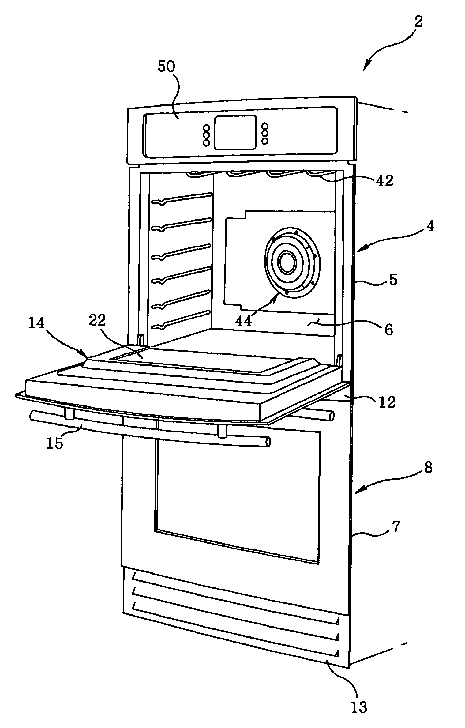
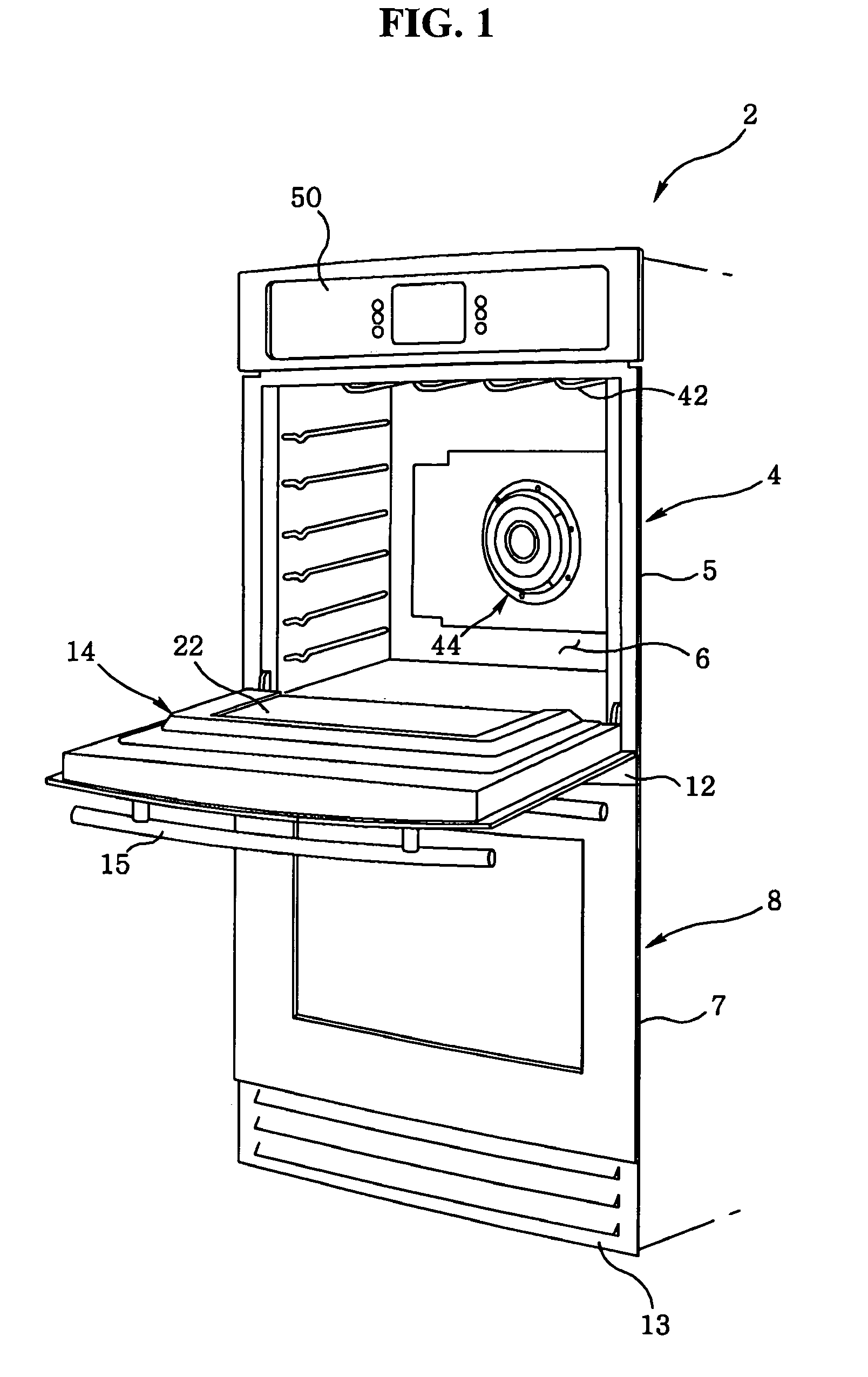
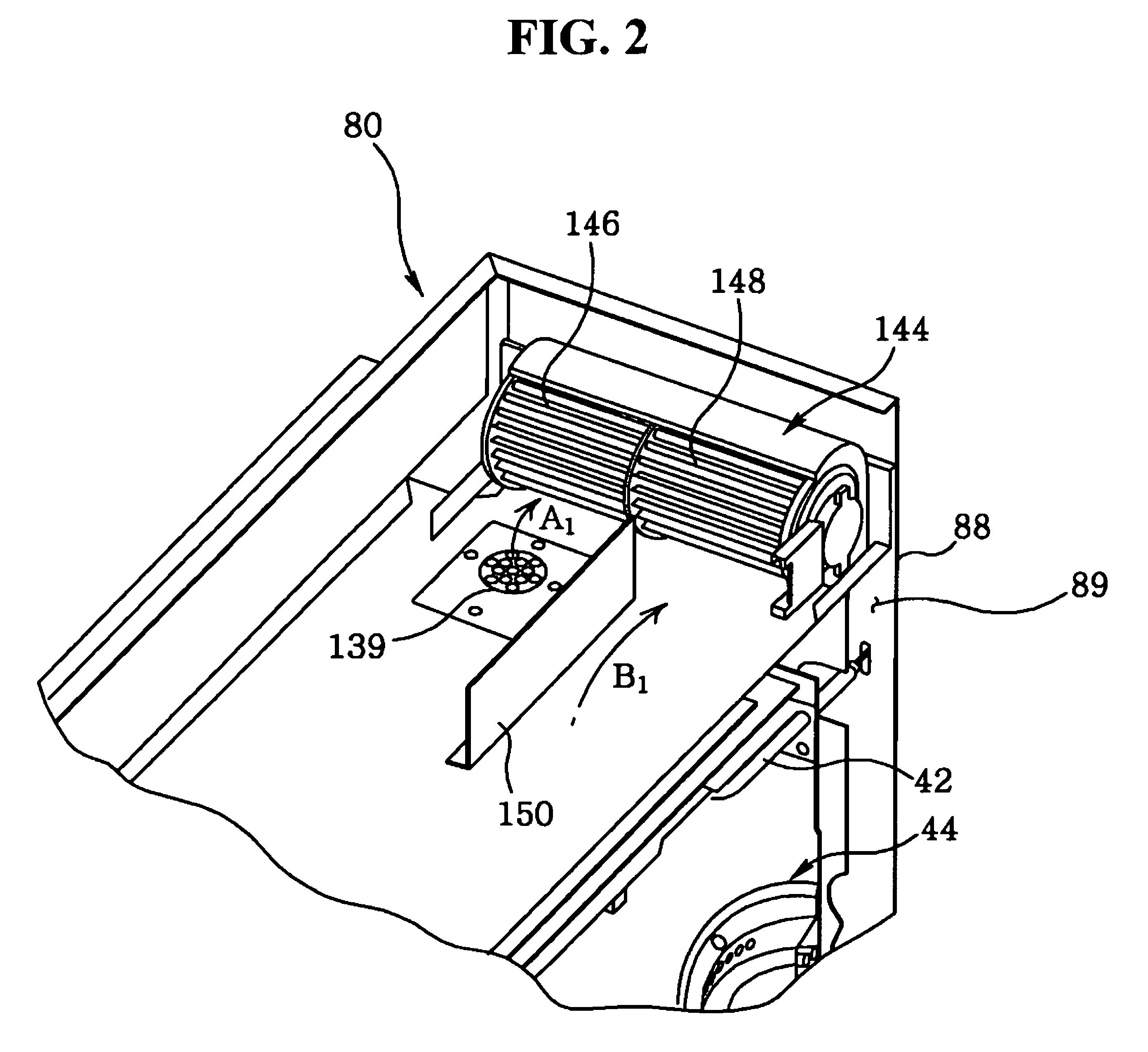
[0034]FIG. 4 illustrates a perspective view of a rear side of a dual electric oven having implemented with a cooling and exhaust system according to an exemplary embodiment of the present invention, FIG. 5 illustrates a partial cross-sectional view of the dual electric oven shown in FIG. 4, and FIG. 6 illustrates flow of cooling air and hot exhaust air passed through a first fan and a second fan shown...


PUM


Abstract

A cooling and exhaust system of a dual oven has upper and lower ovens, in which, in one aspect, an installation structure of a cooling fan and an exhaust structure provided for respectively cooling and exhausting the upper and lower ovens may be integrated into a simplified structure having common components to increase the manufacturing productivity. In another aspect, fans provided at the upper and lower ovens may be independently controlled to operate at different speeds according to a desired operation to maximize the cooling efficiency.

Description

[0001]This application claims the benefit of Korean Patent Application No. 10-2007-0085763, filed on Aug. 24, 2007, which is hereby incorporated by reference in its entirety.BACKGROUND[0002]1. Field of the Disclosure[0003]The disclosure relates to a dual oven, and more particularly, to a cooling and exhaust system of a dual oven having upper and lower ovens, in which an installation structure of a cooling fan and an exhaust structure provided for respectively cooling and exhausting the upper and lower ovens may be integrated into a simplified structure. For instance, common components may be used to increase the manufacturing productivity, and fans provided in the upper and lower ovens may be independently controlled to operate at different speeds according to a desired operation in order to maximize the cooling efficiency.[0004]2. Description of the Related Art[0005]Generally, electric ovens are used for cooking food placed in its cooking chamber using heat generated by a ceramic h...

Claims


Application Information

Patent Timeline
Patent Type & Authority Patents(United States)
IPC IPC(8): F24C15/32
CPCF24C15/2007F24C15/006F24C7/08
Inventor KIM, WAN SOONAM, HYEUN SIKYANG, JAE KYUNGKWAG, DONG SEONGCHO, SEONG HO
Owner LG ELECTRONICS INC
Why Eureka
Try Eureka