Power supply apparatus

a technology of power supply apparatus and power supply device, which is applied in the direction of electrical apparatus, electrochemical generators, fuel cells, etc., can solve the problems of subsequent recovery of power generation capacity, unreasonable operation, and inability to detect abnormal drop in voltage generated by each unit, so as to achieve reasonable operation of the power supply apparatus, stabilize the power supply, and reverse the effect of each power cell

Inactive Publication Date: 2013-11-19
SEIKO INSTR INC
View PDF17 Cites 7 Cited by
  • Summary
  • Abstract
  • Description
  • Claims
  • Application Information

AI Technical Summary

Benefits of technology

[0038]According to the present invention, control is exercised such that when the output voltage between the electrodes of each power cell has dropped to a set voltage or lower, this power cell is isolated to halt the supply of power therefrom, and when recovery of outputting capacity of the isolated power cell has been detected, the supply of power from it is resumed. Thus, reversal of the power cell can be prevented and, when its outputting capacity is recovered, its outputting is resumed, whereby the reasonable operation of the power supply apparatus can be achieved, with the reversal of each power cell being prevented.
[0039]According to the present invention, moreover, the terminals of the plurality of power cells configured electrically independently can be selectively connected by the switching elements. Thus, it is easy to combine the power cells in accordance with the load. Consequently, 1) stabilization of power supply by the power supply apparatus, 2) enhancement of long-term reliability of the power cells, and 3) long life of the power supply apparatus can be realized at the same time. The provision of the cells at rest, in particular, renders a long-term continuous operation possible. From this aspect as well, reliability can be increased. That is, load distribution among the plurality of power cells, stable power supply, and long life of the power source can be achieved.

Problems solved by technology

However, the fuel cell apparatus cannot detect an abnormal drop in a voltage generated by each unit cell 110.
With this technology, however, there is the problem that once a power generation cell has generated an abnormal voltage, this power generation cell is continuously isolated, making a reasonable operation impossible.
However, even after an abnormal drop in the generated power for a cause, such as fuel insufficiency, temporary stoppage or halt of power supply often results in the subsequent recovery of power generation capacity.
Thus, it also has problems, such that 1) the structure of the fuel cell apparatus is complicated, 2) the fuel cell apparatus is upsized, and 3) the weight of the fuel cell apparatus is increased.
In this case, the effect of stabilizing the generated power due to control for increasing or decreasing fuel supply is not obtained, causing the problem of wasteful fuel supply and fuel consumption.

Method used


Image

  • Power supply apparatus
  • Power supply apparatus
  • Power supply apparatus

Examples


first embodiment

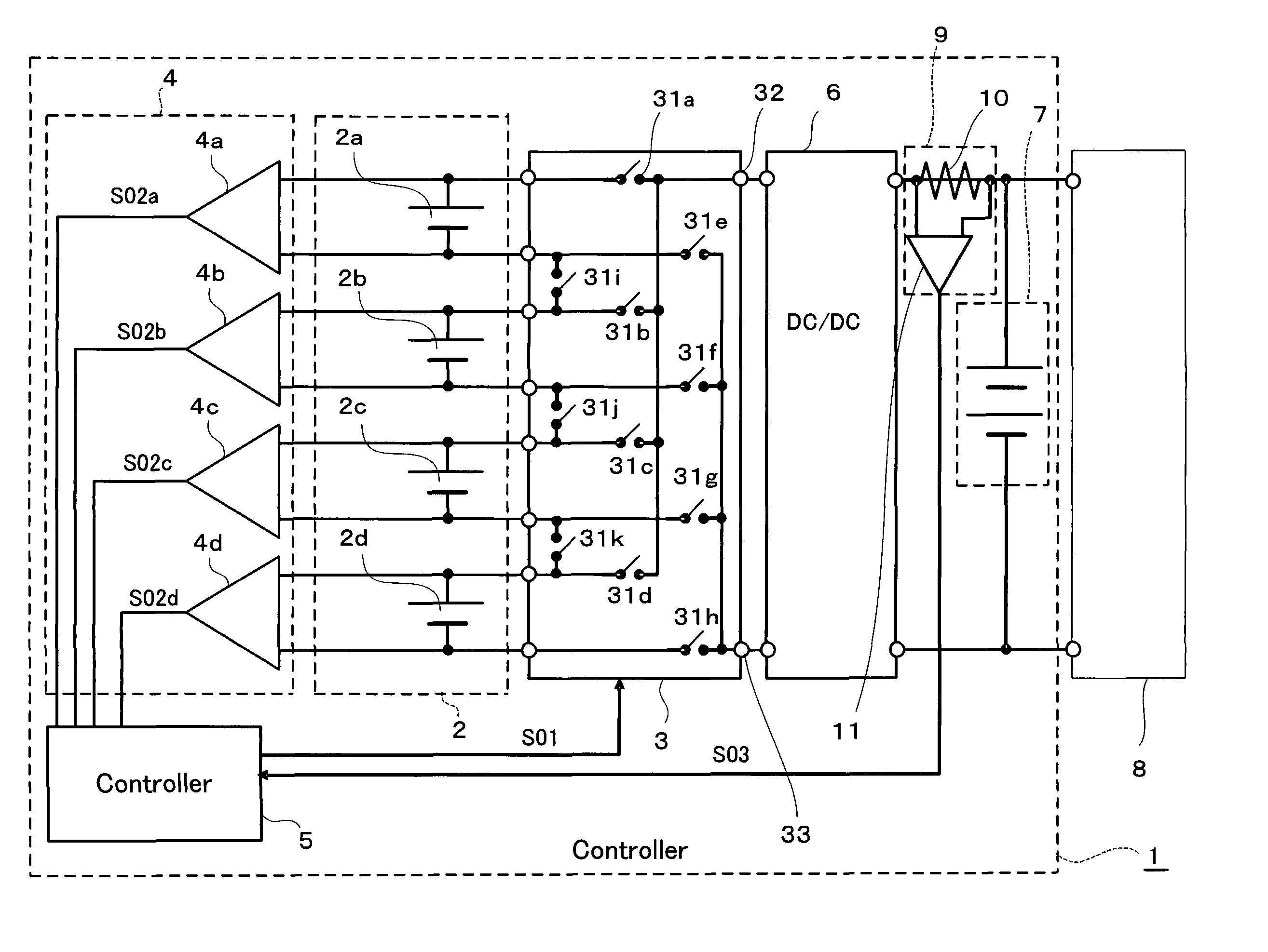
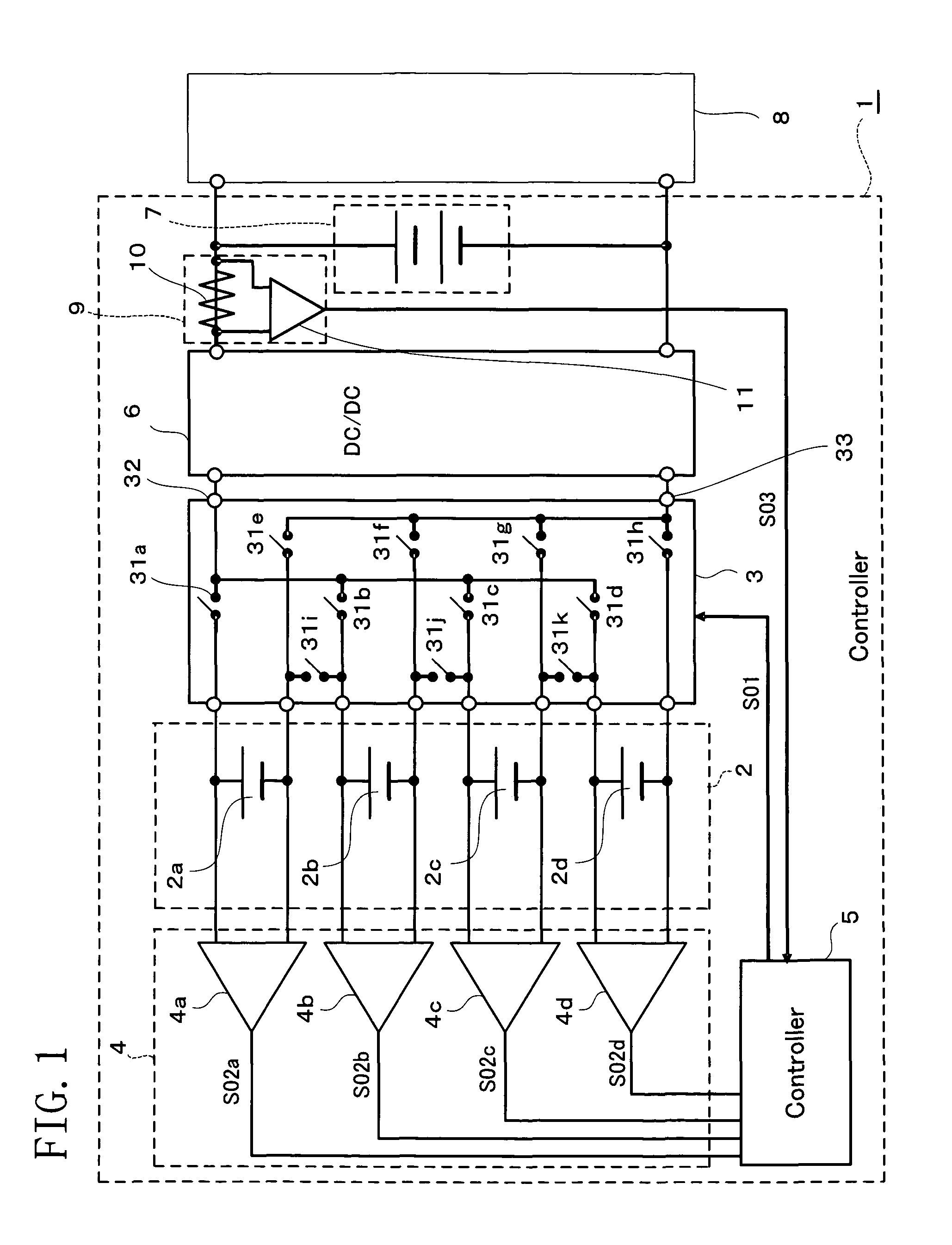
[0063]FIG. 1 is a block diagram showing a power supply apparatus according to a first embodiment of the present invention. As shown in the drawing, a power supply apparatus 1 according to the present embodiment has a fuel cell 2 equipped with a plurality of power generation cells 2a, 2b, 2c, 2d as power cells; a switch 3 for switching, as appropriate, the terminals of the power generation cells 2a to 2d and connecting them; a voltage detector 4 for measuring voltages between the terminals of the power generation cells 2a to 2d; a controller 5 for exercising control for changing connection paths of the switch 3 based on output signals of the voltage detector 4 and a current detector 9; a voltage regulator 6 for stabilizing a voltage supplied to a load 8; a charge and discharge device 7 capable of electrical charging and discharging; and a current detector 9 composed of a current detecting amplifier 11 for detecting a load current.

[0064]In further detail, the power generation cells 2a...

second embodiment

[0110]FIG. 6 is a block diagram showing a power supply apparatus according to a second embodiment of the present invention. As shown in the drawing, a power supply apparatus 21 according to the present embodiment has the configuration of the voltage detector 4 modified to serve as a voltage detector 41. That is, the voltage detector 41 in the present embodiment has an analog multiplexer 42 connected to the output ports of a plurality of power generation cells 2a to 2d, and switches over time (scans) the power generation cells 2a to 2d whose voltages are to be detected. A voltage detecting amplifier 43 is connected to the output port of the analog multiplexer 42. Voltage signals S02a to S02d of the power generation cells 2a to 2d are sequentially supplied to a controller 51 via the voltage detecting amplifier 43. Control of scanning on this occasion is exercised by the controller 51 via a control signal S04. By the action of the controller 51, scanning of the power generation cells 2...


PUM

PropertyMeasurementUnit
output voltageaaaaaaaaaa
voltageaaaaaaaaaa
poweraaaaaaaaaa

Abstract

A power supply apparatus has a combined power source with power cells configured electrically independently. A switch arbitrarily changes connection paths of the power cells by selectively connecting power cell terminals through switching elements. A voltage detector detects differences in electrical potentials between the power cell terminals. A controller controls ON-OFF states of the switching elements by controlling the switch by a control signal generated based on voltage signals representing the differences in electrical potentials detected by the voltage detector so as to isolate one of the power cells to stop a supply of electric power therefrom when a voltage generated in the power cell has dropped to a specified voltage or lower. The controller restarts the supply of electric power from the power cell whose power supply has been stopped when the duration of a down time of the power cell has reached a predetermined time or longer.

Description

CROSS-REFERENCE TO RELATED APPLICATIONS[0001]This application is a U.S. national stage application of International Application No. PCT / JP2008 / 059878 filed May 29, 2008, claiming a priority date of Jul. 10, 2007, and published in a non-English language.BACKGROUND OF THE INVENTION[0002]1. Technical Field[0003]This invention relates to a power supply apparatus and, more specifically, to a power supply apparatus for preventing a pole change or reversal of a plurality of power cells configured electrically independently, while continuing their reasonable operation, and for performing a reasonable operation conforming to a load power.[0004]2. Background Art[0005]FIG. 7 is a block diagram showing a fuel cell apparatus according to a conventional technology (Patent Document 1). As shown in this drawing, the fuel cell apparatus is designed to supply electric power, which has been generated in a fuel cell stack 100, to a load 109 via a power converter 103 for regulating the electric power to...

Claims


Application Information

Patent Timeline
Patent Type & Authority Patents(United States)
IPC IPC(8): H01M8/04
CPCH01M8/04552H01M8/04604H01M8/0494H01M8/04955H01M8/04671H01M8/1011H01M2008/1095Y02E60/50H02J7/0016
Inventor YANASE, NORIMASAISHISONE, NOBORUTAMACHI, TSUNEAKIOZAKI, TORUSARATA, TAKAFUMIYUZURIHARA, KAZUTAKAIWASAKI, FUMIHARU
Owner SEIKO INSTR INC
Why Eureka
Try Eureka