
Wavelength division multiplexing transmission system and apparatus and optical signal noise ratio calculation method

a transmission system and wavelength division technology, applied in the field of wavelength division multiplexing transmission systems, wavelength division multiplexing transmission apparatuses, optical signal noise ratio calculation methods, can solve the problems of inability to accurately measure osnr, inability to obtain accurate noise optical power, and increase of bit error rate (ber), so as to reduce the effect of sideband

Inactive Publication Date: 2013-11-19
FUJITSU LTD
View PDF4 Cites 8 Cited by
  • Summary
  • Abstract
  • Description
  • Claims
  • Application Information

AI Technical Summary

Benefits of technology

[0011]In this background, a general purpose of the present invention is to provide a transmission system or the like that can measure the OSNR accurately.
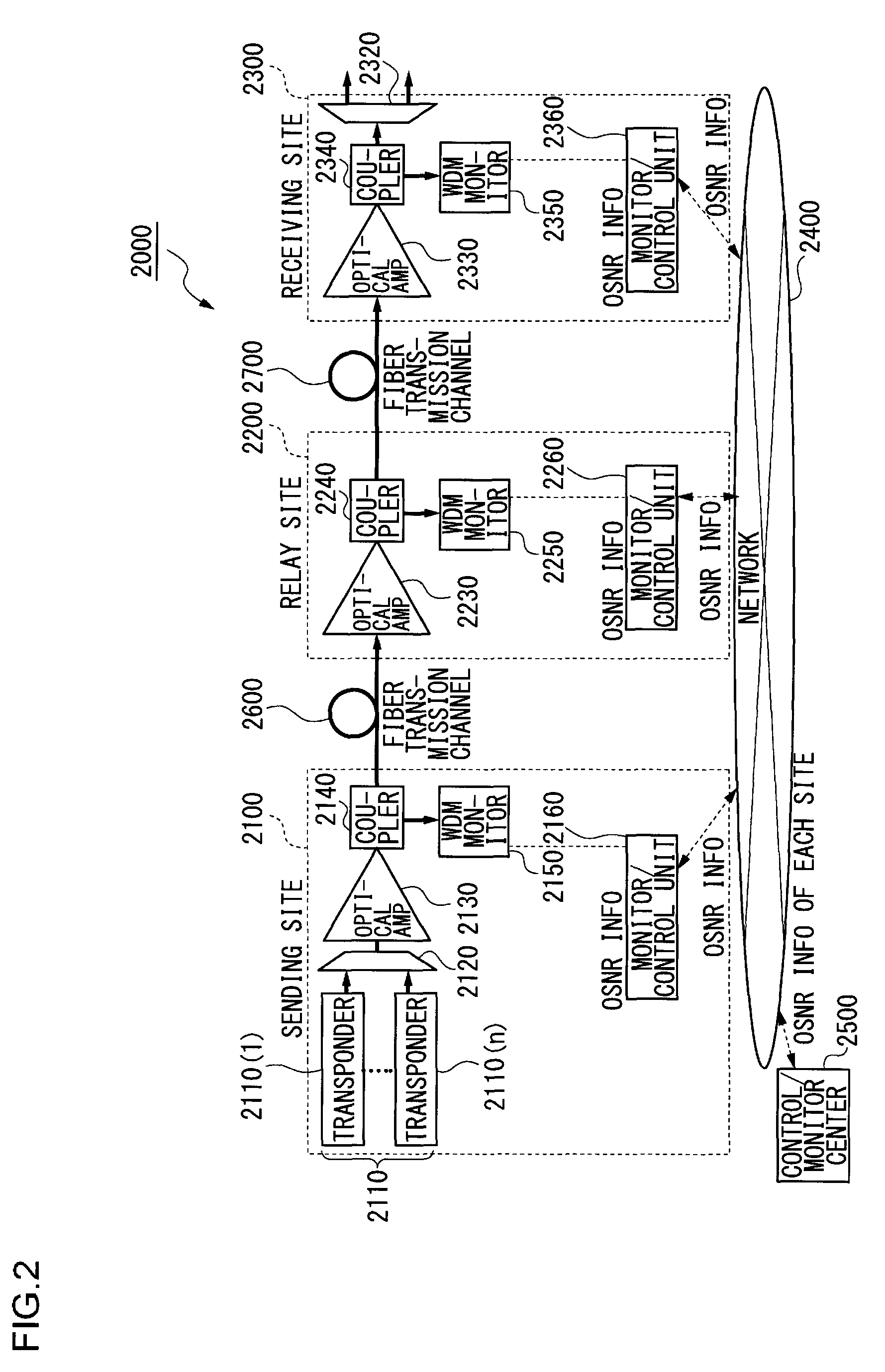
[0025]Yet another embodiment of the present invention relates to a wavelength division multiplexing (WDM) transmission apparatus for transmitting a wavelength division multiplexed signal light. The apparatus comprises: an optical amplifier that amplifies a transmitted signal light; an optical branching unit that branches the signal light amplified by the optical amplifier; and a WDM monitor that measures a first optical signal noise ratio (OSNR) of the signal light branched by the optical branching unit. The apparatus subtracts from the first OSNR measured by the WDM monitor a second OSNR ascribed to a sideband of the signal light provided from the source of the signal light so as to compute an OSNR of an ASE noise light with a reduction of an effect of the sideband.

Problems solved by technology

In a system employing EDFA, amplified spontaneous emission (ASE) is generated becoming noise causing bit error rate (BER) increases.
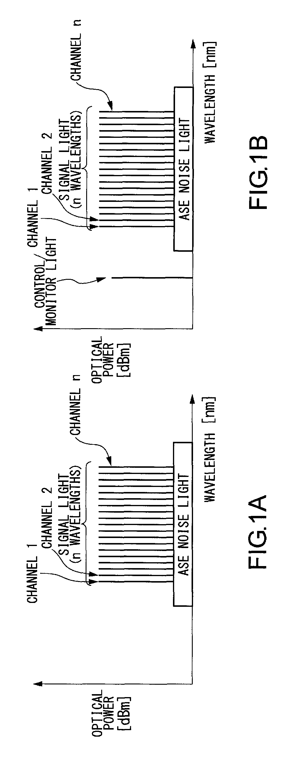
Hence, it is hard to acquire a wavelength point where only the noise component can be measured without suffering from the effect of the modulated sideband component of the transmission signal so that an accurate noise optical power cannot be obtained.
Thus there exists such a problem that the OSNR cannot be accurately measured under these circumstances.

Method used


Image

  • Wavelength division multiplexing transmission system and apparatus and optical signal noise ratio calculation method
  • Wavelength division multiplexing transmission system and apparatus and optical signal noise ratio calculation method
  • Wavelength division multiplexing transmission system and apparatus and optical signal noise ratio calculation method

Examples


first embodiment

[0067][First Embodiment]

[0068]FIG. 4 to FIG. 6 are block diagrams illustrating the structure of WDM transmission systems according to some embodiments of the present invention. The same reference numerals used in FIG. 4 to FIG. 6 denote the same elements in FIG. 2 and FIG. 3 and thus a detailed explanation of such elements is omitted. In the WDM transmission systems shown in FIG. 4 to FIG. 6, a wavelength multiplexer (also referred to as a mux / demux) at a sender site wavelength-multiplexes each signal light from transponders, and a coupler (also referred to as an optical branching unit), which is arranged in front of an optical fiber, branches the wavelength-multiplexed optical signal to give the branched signal to a WDM monitor.

[0069]In the WDM transmission system 4000 in FIG. 4, the transmission apparatus 4100 at the sender site obtains OSNRsn information from the signal light branched by the coupler 2140 in front of the optical amplifier 2130. Hereinafter, the lowercase character...

second embodiment

[0097][Second Embodiment]

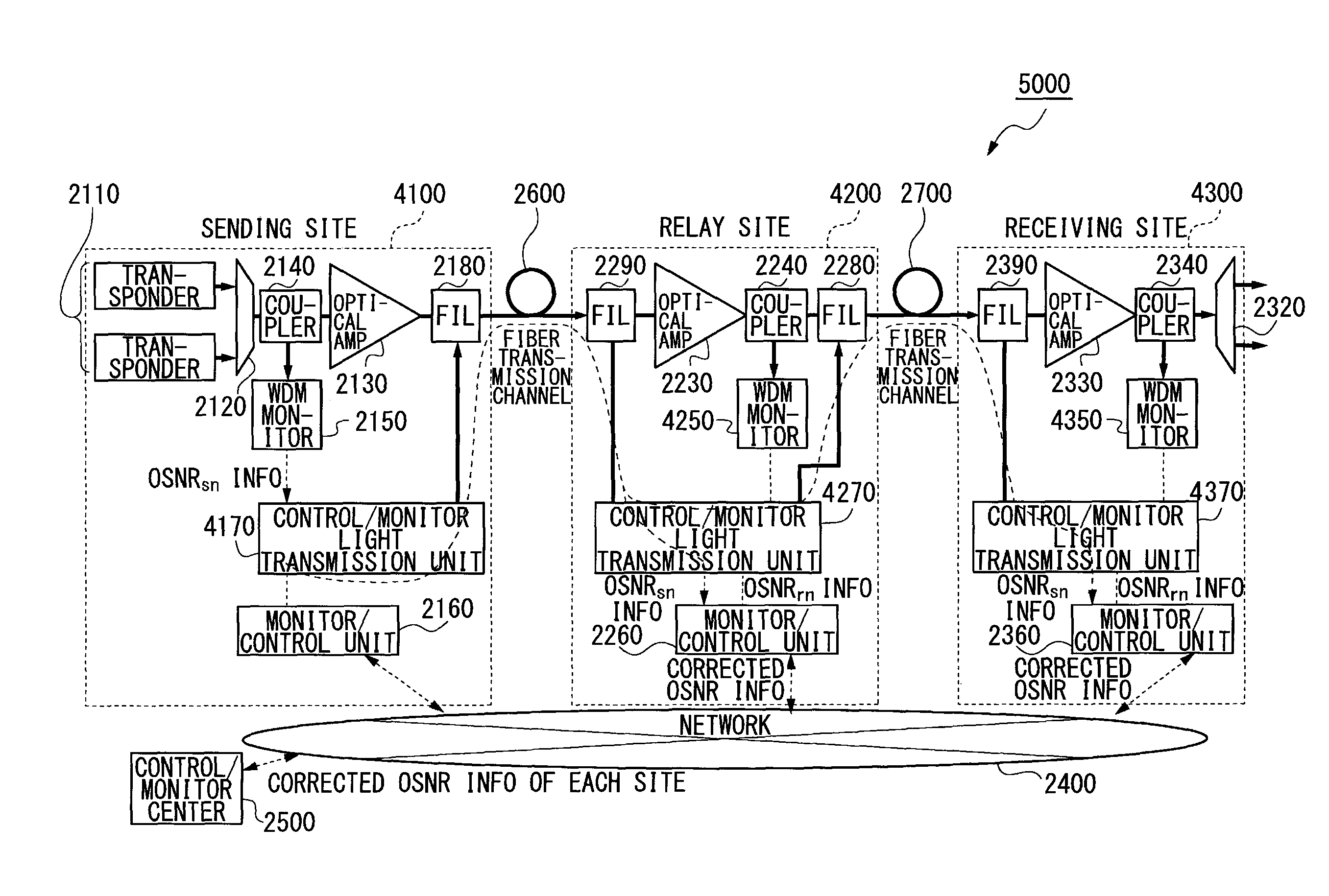
[0098]The WDM transmission systems 4000 and 5000 shown in FIG. 4 and FIG. 5 respectively are of a typical structure for notifying the OSNRsn information to the downstream transmission apparatus 4200, 4300 of the relay site or the receiving site by using the control / monitor light. On the other hand, the WDM transmission system 6000 of FIG. 6 is of a typical structure for notifying the OSNRsn information to the downstream relay site or receiving site via the monitor / control units 2260, 2360 and the network 240.

[0099]The WDM transmission system 5000 of FIG. 5 differs from the WDM transmission system 4000 in that the OSNRsn information received via the control / monitor light transmission units 4170 and 4270 is notified to the monitor / control unit 2260 and the process for computing the corrected OSNRn is performed in the monitor / control unit 2260.

[0100]In the WDM transmission system 5000, the WDM monitor 4250 is not notified of the OSNRsn information and the WDM m...

third embodiment

[0104][Third Embodiment]

[0105]FIG. 15 is a block diagram illustrating the WDM transmission system 14000 where the light is branched from the coupler 2140 attached to the output terminal of the optical amplifier 2130 in the transmission apparatus e100 of the sending site and the branched light is input to the WDM monitor 2150. The WDM transmission system 14000 is preferable in that the common arrangement and structure of the optical amplifiers 2230, 2330 and the couplers 2240, 2340 in the transmission apparatuses e200, e300 of the relay site and the receiving site can be adopted.

[0106]In the WDM transmission system 14000 shown in FIG. 15, the OSNRs′n measured by the WDM monitor 2150 contains the ASE component of the optical amplifier 2130 that corresponds to a sending amplifier. The measurement unit is dB and “n” indicates the channel number (1 to the number of the wavelengths).

[0107]Therefore, the value of OSNR″n that corresponds to the ASE component of the optical amplifier 2130 is...


PUM


Abstract

A wavelength division multiplexing (WDM) transmission system for transmitting a wavelength division multiplexed signal light from a sender transmission apparatus to a receiver transmission apparatus is provided. The system comprises a computing unit that subtracts from a first optical signal noise ratio (OSNR) of the signal light measured by the receiver transmission apparatus a second OSNR ascribed to a sideband of the signal light measured by the sender transmission apparatus so as to compute a corrected OSNR of an amplified spontaneous emission (ASE) noise light with a reduction of an effect of the sideband.

Description

BACKGROUND OF THE INVENTION[0001]1. Field of the Invention[0002]The present invention relates to a wavelength division multiplexing transmission system, a wavelength division multiplexing transmission apparatus, and an optical signal noise ratio calculation method used for the system and apparatus.[0003]2. Description of the Related Art[0004]Due to an increased volume of communicated information, a high capacity and low cost optical fiber communication system has been developed. In such a system, a wavelength division multiplexing (WDM) method for multiplexing multiple wavelengths and transmitting the multiplexed signal has been adopted and the degree of wavelength-multiplexing tends to increase higher and higher in recent years.[0005]Channel spacing, an index of the degree of wavelength-multiplexing, has been standardized by the International Telecommunications Union Telecommunications Standardization Sector (ITU-T). It is known that a standard WDM system wavelength-multiplexes a s...

Claims


Application Information

Patent Timeline
Patent Type & Authority Patents(United States)
IPC IPC(8): H04J14/02H04B10/077H04B10/07H04B10/079H04J14/00
CPCH04B10/07953H04J14/0221H04J14/02H04J14/0219
Inventor HIRAIZUMI, MAKI
Owner FUJITSU LTD
Learn More