Liquid diffuser device

a diffuser device and liquid technology, applied in the field of irrigation systems, can solve the problems of high risk of uneven deflection of the jet, deformation of the spherical element, efficiency loss, etc., and achieve the effect of substantially unchanged plate distance from the passageway with tim

Active Publication Date: 2013-11-26
KOMET AUSTRIA GMBH
View PDF13 Cites 5 Cited by
  • Summary
  • Abstract
  • Description
  • Claims
  • Application Information

AI Technical Summary

Benefits of technology

[0015]The object of this invention is to overcome the above drawbacks, by providing a diffuser device that has a simple and efficient construction and is relatively cost-effective.
[0016]Another object of the present invention is to provide a diffuser device that allows a constant distance to be maintained between the deflecting plate and the jet delivery nozzle, thereby ensuring optimal device operation, even after long use.
[0020]Thus, the intermediate member will prevent even the slightest downward shift of the stem, and hence of the plate secured thereto, consequent to wear of the contact surface, thereby keeping the distance of the plate from the passageway substantially unchanged with time.

Problems solved by technology

These solutions have the apparent drawback of not allowing constant coupling of the surface and the rolling track, which results in a high risk of the jet being unevenly deflected.
Furthermore, the normal operating pressures exerted by the jet on the deflector body cause deformations of the two contact surfaces, resulting in an efficiency loss.
However, also in this case, normal operating pressures may cause deformation of the spherical element and, as a result, a downward shift, even though to a little extent, of the deflector body.
Thus, the distance of the plate from the nozzle will be longer than the optimal device calibration distance, and the jet will not be optimally deflected.
However, also in this case, the deformations of the various spherical components, caused by jet pressure, may cause a change of the initial orientation of the device, resulting in an inefficient operation thereof.
Furthermore, the roller cage is greatly susceptible to the building up of foreign matter, i.e. dust and sand, with a high risk of irregular operation, which might also lead to total blockage.

Method used


Image

  • Liquid diffuser device
  • Liquid diffuser device
  • Liquid diffuser device

Examples


Embodiment Construction

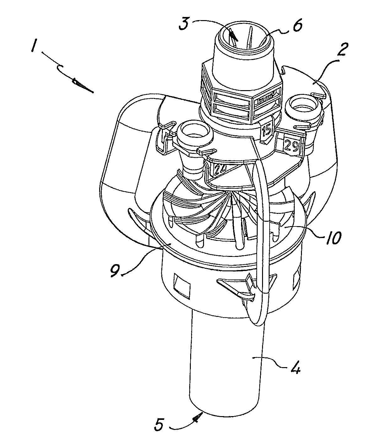
[0026]Referring to the above figures, the diffuser device of the invention, generally designated by numeral 1, may be used to distribute a liquid, e.g. water, over surfaces, possibly having a very large surface area, such as in the irrigation of agricultural areas.

[0027]The device may be connected to a hydraulic system, not shown, for liquid delivery and may be mounted, alone or in combination with other similar devices, to a stationary or rotating support arm, also not shown, to be set at a predetermined height, according to the desired jet length.

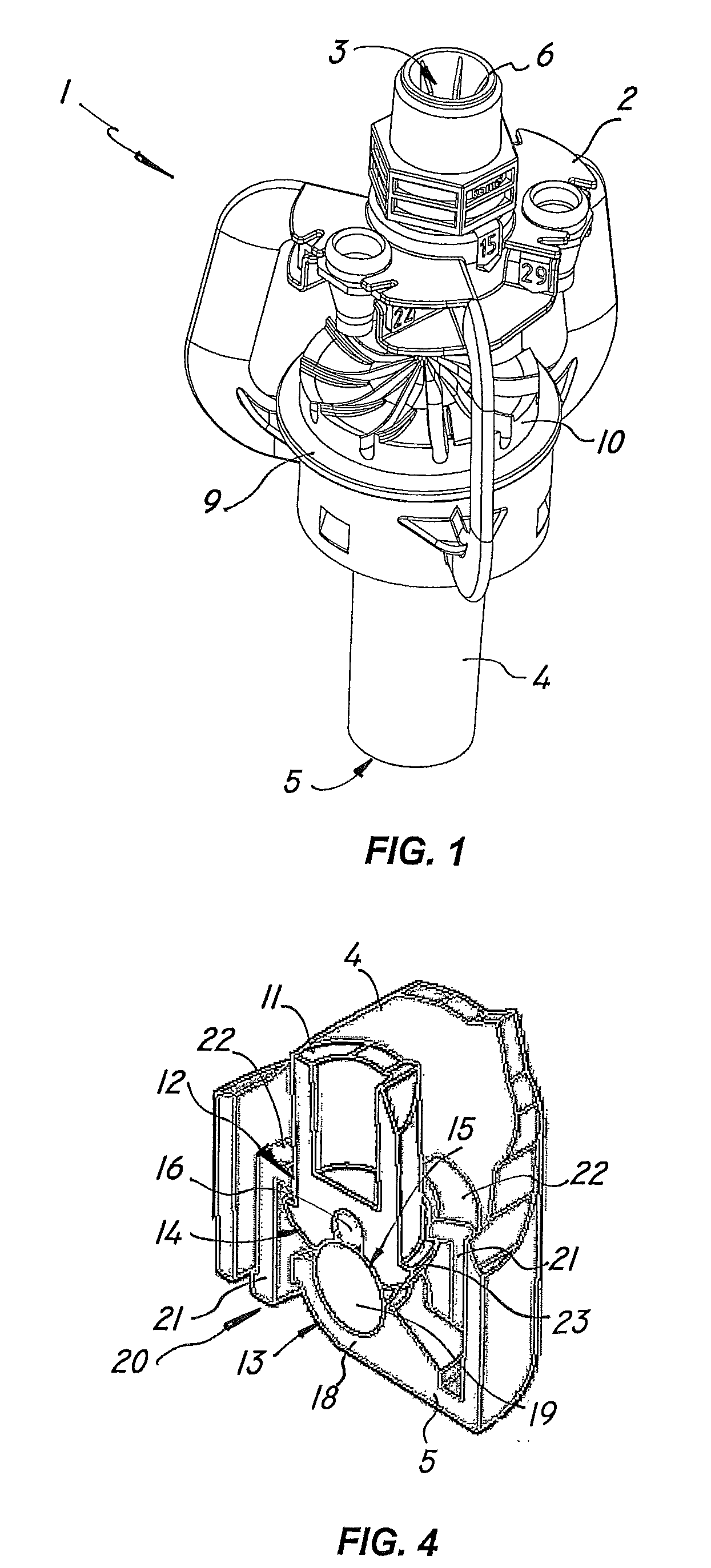
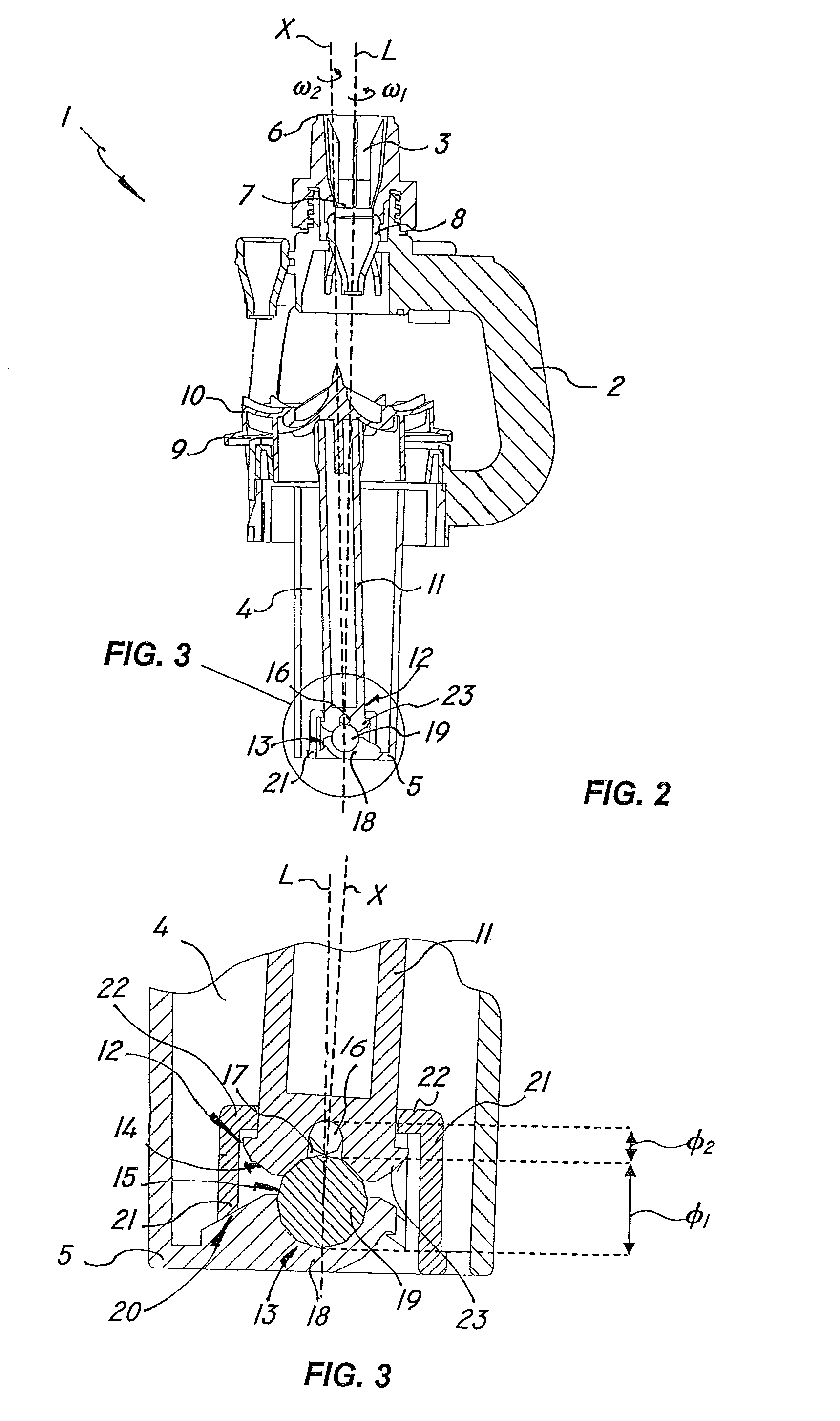
[0028]According to the invention, a liquid diffuser device comprises a support frame 2 having an upper passageway 3 to direct a liquid jet in a predetermined direction and a lower hollow tubular body 4 defining a first longitudinal axis L and having a substantially transverse bottom wall 5.

[0029]The frame 2 may be connected to the irrigation system at the inlet 6 of the upper tubular passageway 3 and be equipped, at the outlet 7, with a f...


PUM


Abstract

A liquid diffuser device, comprising a support frame (2) with an upper passageway (3) to direct a liquid jet and a lower hollow tubular body (4) with a bottom wall (5), a liquid jet deflecting member (9) having an upper plate (10) fixed to a lower stem (11) which is had within the tubular body (4), means (13) for movably coupling the stem (11) to the bottom wall (5), comprising at least one lower contact surface (14) of the stem (11) and at least one upper contact surface (15) of the bottom wall (5). The movable coupling means (13) comprise an intermediate contact member (16) secured to the lower end portion (12) of the stem (11), and continuously contacting the upper surface (15) of the bottom wall (5) to avoid downward shifting of the stem (11) consequent to wear of the contact surfaces (14, 15).

Description

FIELD OF THE INVENTION[0001]The present invention generally finds application in the field of irrigation systems for agricultural and industrial applications, and particularly relates to a liquid diffuser device.BACKGROUND ART[0002]Liquid diffuser devices as used in irrigation systems for delivery of water or other liquids, commonly known as “sprinklers”, comprise a support frame which is designed to be connected to the hydraulic system and has a nozzle for directing the liquid jet to a specially shaped diffusion plate.[0003]The latter is in turn mounted to a deflecting member, having a rotating stem of such a size as to move, under jet pressure, with a combined motion of rotation about its own central axis and rotation or precession about the jet-defined axis, for uniform peripheral deflection of the jet.[0004]In certain prior art solutions, as described for instance in U.S. Pat. No. 5,950,927 and U.S. Pat. No. 6,176,440, the stem has a lower portion formed with a conical or sphero...

Claims


Application Information

Patent Timeline
Patent Type & Authority Patents(United States)
IPC IPC(8): B05B3/04B05B3/02F23D11/04
CPCB05B3/008B05B3/0486B05B15/18
Inventor DRECHSEL
Owner KOMET AUSTRIA GMBH
Why Eureka
Try Eureka