Extended term patient resuscitation/ventilation system

a patient resuscitation and ventilator technology, applied in the field of extended term patient resuscitation/ventilation system, can solve the problems of limiting the operating time of compressed gas cylinders, and achieve the effect of increasing patient blood flow and smoothing out pressure fluctuations

Inactive Publication Date: 2013-11-26
AUTOCPR
View PDF37 Cites 14 Cited by
  • Summary
  • Abstract
  • Description
  • Claims
  • Application Information

AI Technical Summary

Benefits of technology

[0006]A patient resuscitation system, in accordance with the present invention, includes a plurality of inflatable cuffs adapted to extend around separate portions of a patient's anatomy (e.g, chest, abdomen and legs) for increasing the patient's blood flow when periodically inflated / deflated (1) to achieve ROSC and subsequently (2) to continue the support of his / her circulatory system. A timer, such as the timer disclosed in the '278 pub., sets the inflation / deflation periods. Air for the inflation steps is provided by a primary low-pressure-high-volume-air-compressor connected to a volume chamber (i.e. to smooth out pressure fluctuations). A pneumatic circuit, including a pressurized gas source, such as a secondary compressor, provides a separate pneumatic control signal associated with each cuff bracketing each inflation period set by the timer. An air handler is individually connected between each cuff, the volume chamber and the atmosphere (or ambient) and responsive to the pneumatic control signals for inflating / deflating each cuff in accordance with the inflation / deflation periods set by the timer.

Problems solved by technology

While it is believed to be cutting edge for its intended purpose, the use of compressed gas cylinders limits its operating time.

Method used


Image

  • Extended term patient resuscitation/ventilation system
  • Extended term patient resuscitation/ventilation system
  • Extended term patient resuscitation/ventilation system

Examples


Embodiment Construction

Overview of the System Operating in an Exemplary Mode

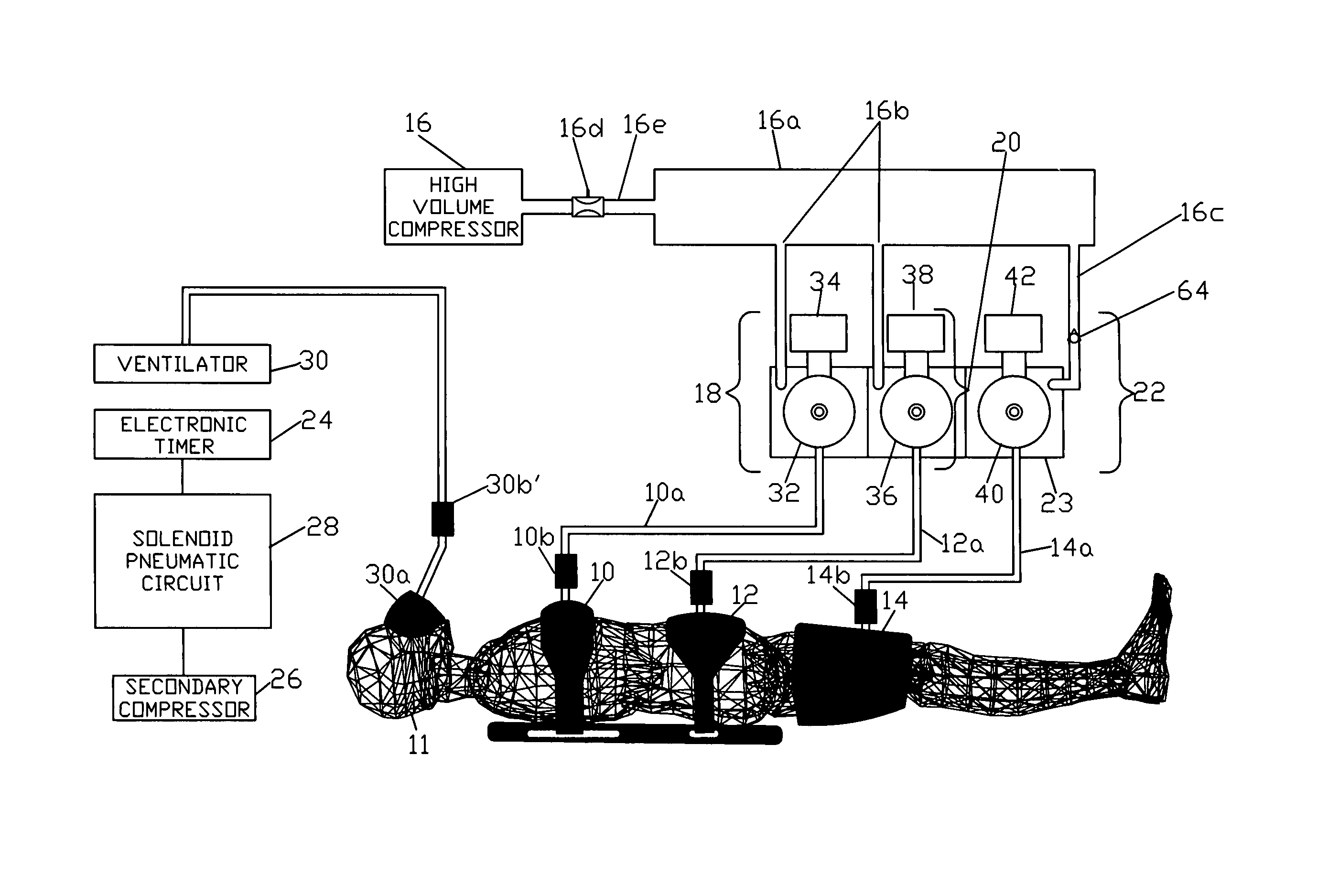
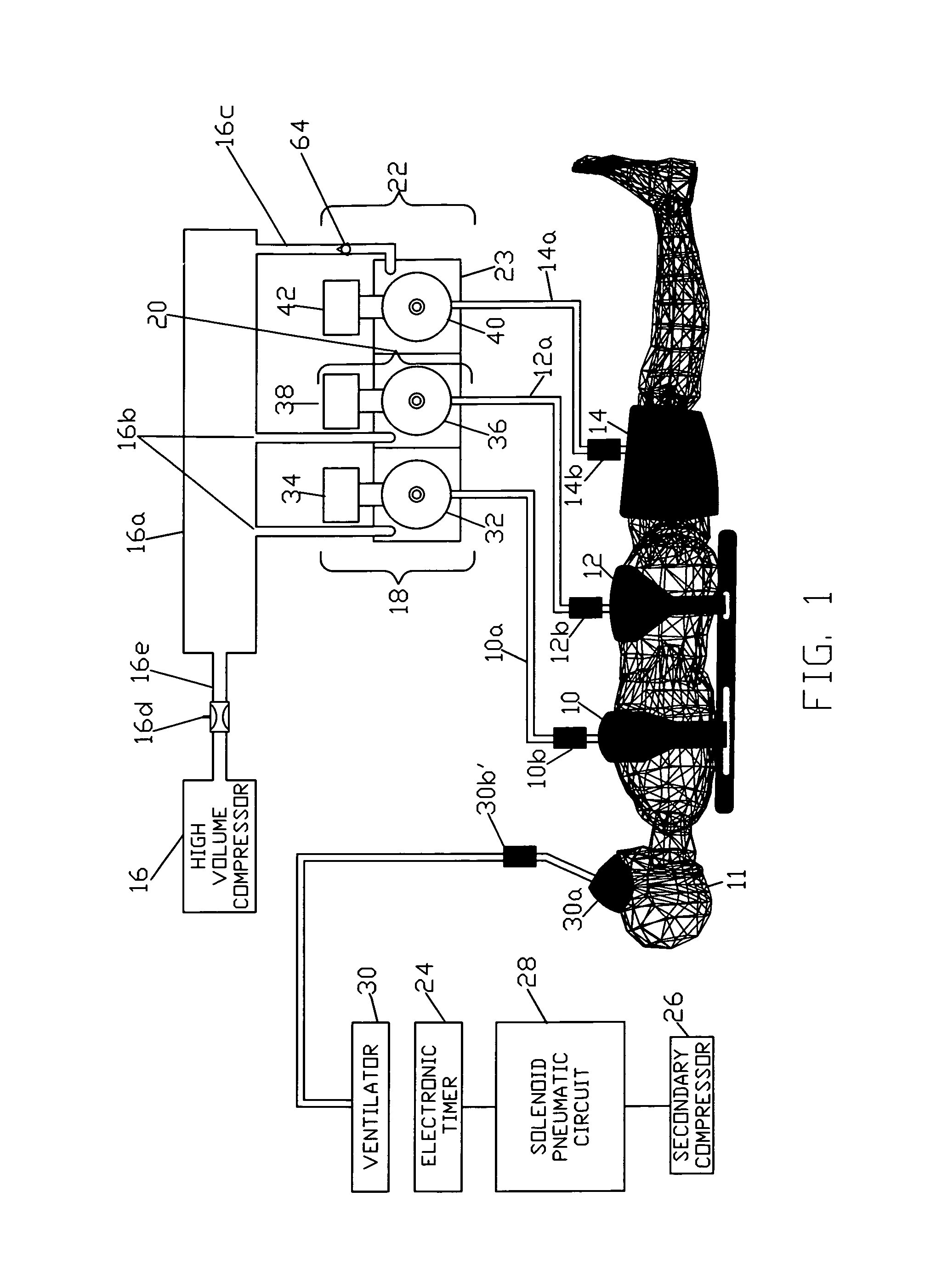
[0027]Referring now to FIG. 1 a patient 11, shown in reclining position, is fitted with a chest cuff 10, abdominal cuff 12 and leg cuffs 14. A primary low-pressure-high-volume-compressor 16 supplies air to a volume chamber 16a (for smoothing out pressure fluctuations resulting from the periodic inflation of the cuffs). The volume chamber is connected to air handlers 18 (chest) and 20 (abdomen) via lines 16b and to air handlers 22 (legs) via line 16c and back flow valve 64, to be described. A suitable compressor may be obtained from the Parker Hannifin Corporation under part no. 737-23-01. An adjustable flow restrictor 16d connected between the compressor and the volume chamber (in line 16e) controls the flow rate to the volume chamber to say about 150 l / min. A pressure compensated relief valve (to be described) controls the volume chamber pressure, e.g., 2-3 psi. The individual air handlers are mounted in a common manifold block 2...


PUM


Abstract

An extended term resuscitation system includes a plurality of inflatable cuffs adapted to extend around separate portions of the anatomy of a patient (i.e. the chest, abdomen and legs) for enhancing the circulation when inflated/deflated periodically. A primary low-pressure-high-volume air compressor is in fluid communication with each of the cuffs through individual air handlers. The air handlers are formed with an inflation and a deflation diaphragm valve which, under the control of an electronic timer and a pneumatic circuit, connect the respective cuff to the output of the compressor for inflation or to the atmosphere for deflation. A secondary air compressor provides air under suitable pressure to the pneumatic circuit for the control of the diaphragm valves. As an option the operator may change the cyclical rate and cuff pressure. A ventilator provides oxygen to the patient in selected volumes or on demand.

Description

FIELD OF THE INVENTION[0001]This invention relates to an apparatus or system for providing cardiac and / or pulmonary resuscitation and more particularly to such a system that is automated and capable of enhancing a patient's circulation and ventilation for an extended period.BACKGROUND OF THE INVENTION[0002]State of the art methods and apparatus for providing external cardiac resuscitation are discussed to some extent in U.S. Pat. No. 5,806,512 (“'512 patent”). The '512 patent teaches the use of inflatable cuffs surrounding a patient's chest, abdomen and legs which are periodically inflated and deflated to force blood from the extremities to and through the heart with the chest and abdomen functioning in an out-of-phase relationship. Ventilation via a patient mask is also disclosed in the patent.[0003]More recently a portable resuscitation / ventilation system using inflatable chest, abdominal and leg cuffs and a ventilator coupled to self-contained cylinders of compressed gas is descr...

Claims


Application Information

Patent Timeline
Patent Type & Authority Patents(United States)
IPC IPC(8): A61H31/00A62B9/02
CPCA61H31/00A61H9/0078A61H2205/083A61H2201/1619A61H2201/1628A61H2201/164A61H2201/5002A61H2205/084A61H2205/108Y10T137/87169
Inventor FLOOD, MICHAEL G.KOTALIK, RICHARD J.RULIFSON, DONALDHAMILTON, ROBERT M.
Owner AUTOCPR
Why Eureka
Try Eureka