
Radiator and air cooler mister

a technology of air cooler and radiator, which is applied in the direction of machines/engines, combustion types, lighting and heating apparatus, etc., can solve the problems of liquid boil-over situation, severe engine damage, and limited space for mounting such devices in most automotive applications, so as to reduce the routine for replenishing and extend the liquid's operational range

Inactive Publication Date: 2013-12-03
VEHICLE ENHANCEMENT LABS
View PDF12 Cites 6 Cited by
  • Summary
  • Abstract
  • Description
  • Claims
  • Application Information

AI Technical Summary

Benefits of technology

The system effectively extends the operational range of the cooling liquid, reduces replenishment frequency, and provides additional cooling protection by maintaining engine temperatures within safe limits, preventing overheating and potential engine damage.

Problems solved by technology

Under extreme temperature conditions, over-expansion of the liquid can occur and can potentially lead to a liquid boil-over situation.
It is under these conditions if engine operations are not shut down, severe engine damage can result.
In so far as known, other liquid misting methods or apparatus designed for other applications have multiple disadvantages if tried to be adapted to automotive applications:1. Space for mounting such devices in most automotive applications is limited.2. Due to limited reservoir mounting space, recycling of the liquid waste is critical for extending the liquid's replenishment range.3. Electrical power needs to power said devices are limited to Direct Current only and electrical power provided has limitations due to other electrical obligations on the vehicle.4. Other devices require the use of an incorporated fan to blow the liquid misting onto the object requiring cooling.
Vehicles such as RV's and trucks used for towing constantly operate under extreme load demands and are considered a high risk for mechanical break downs due to engine overheating conditions.

Method used


Image

  • Radiator and air cooler mister
  • Radiator and air cooler mister
  • Radiator and air cooler mister

Examples


Embodiment Construction

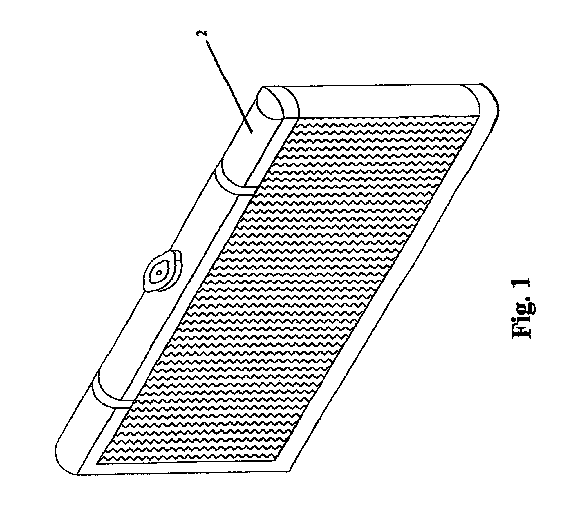
[0017]FIG. 1 illustrates a perspective view of the present invention's related art. The heat exchanger 2 is utilized to cool circulated liquid needed for temperature stabilization in an internal combustion engine or other heat generating drive train components dependent on liquid or air cooling.

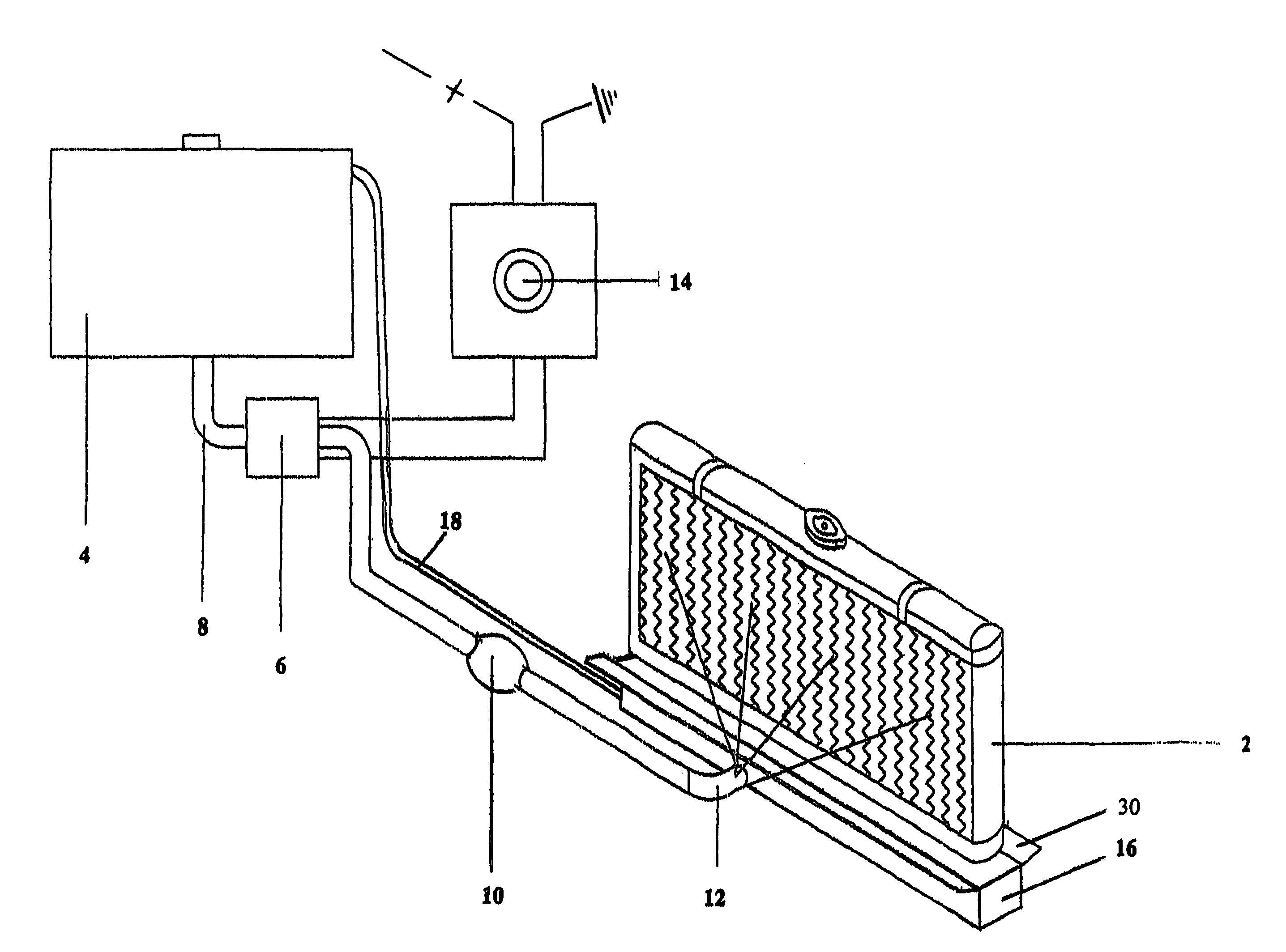
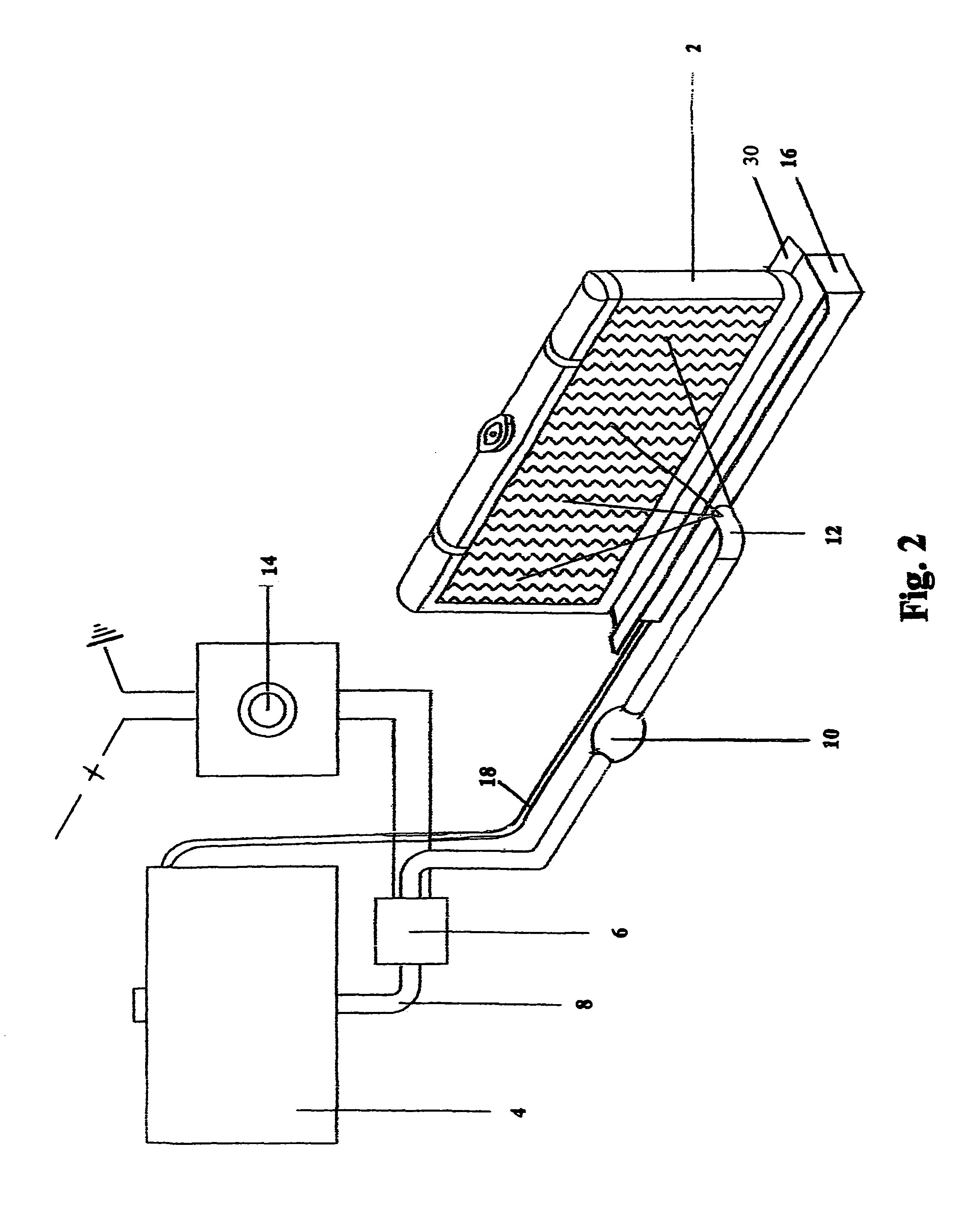
[0018]FIG. 2 illustrates an operational overview of the present invention when utilizing a manually operated electrical switch circuit. An airtight liquid reservoir 4, housing a predetermine amount of liquid is utilized for supplying a mist of water to the frontal area of an automotive heat exchanger 2. A transfer tube or hose 8, transfers the misting liquid via an electrical liquid pump 6 through a directional flow valve 10 prior to exiting out the spray nozzle 12. The spray nozzle 12 mounts inside the grill or air intake area of the vehicle prior to the front of the heat exchanger and is dependant upon incoming air flow to transfer the sprayed liquid mist onto the heat exchanger 2. Electric...


PUM


Abstract

The present invention provides additional cooling assistance for automotive heat exchanging systems used for the cooling of liquids or air needed for engine operations. This operating system utilizes a liquid reservoir, an electric pump, a liquid transfer hose housing a directional flow valve, a spray nozzle, a liquid recycling tray mounted below the heat exchanger, a recycling liquid return hose, an electrical timed pulse relay circuit incorporated into a remotely mounted electrical on and off switch assembly, or the system can be automated with the incorporation of an adjustable thermostatic control sensor circuit. Under extreme operating conditions, a vehicle's engine can reach undesirable operating temperatures and when providing a mist of liquid to the frontal area of the heat exchanger, helps to stabilize or drop the engine's operating temperatures.

Description

BACKGROUND OF INVENTION[0001]1. Field of the Invention[0002]This invention relates to a method and apparatus used strictly for the assisted cooling of external automotive heat exchangers used to cool a liquid or air during operations of an internal combustion engine.[0003]2. Background of Related Art[0004]The present invention relates to automotive engines reliant upon a heat exchanger system for engine heat dissipation. A typical type heat exchanger used for automotive applications is commonly referred to as a radiator which allows air to flow through a series of cooling fins attached to a series of incorporated inner liquid passageways, as air flows through the cooling fins heat is allowed to dissipate from a circulated cooling liquid housed inside these inner passageways. A vehicle when operating under extreme conditions collects heat build up internally within the engine due to internal fuel combustion. This heat is then transferred from the engine's internal metal structure int...

Claims


Application Information

Patent Timeline
Patent Type & Authority Patents(United States)
IPC IPC(8): B05B7/32
CPCF01P9/02
Inventor GREEN, MICHAEL PHILIP
Owner VEHICLE ENHANCEMENT LABS
Learn More