Multi-phase permanent magnet brushless DC electric motor

a brushless dc electric motor and permanent magnet technology, applied in the direction of windings, magnetic circuit shapes/forms/construction, windings, etc., can solve the problems of limited use to low power, low power, and inability to adapt to electrical power regeneration. , to achieve the effect of low voltage, safe use and sufficient volum

Active Publication Date: 2013-12-10
FERRAN ROBERT J
View PDF41 Cites 12 Cited by
  • Summary
  • Abstract
  • Description
  • Claims
  • Application Information

AI Technical Summary

Benefits of technology

[0008]The high horsepower electric motor disclosed herein operates at a sufficiently low voltage to be acceptable for marine use and which distributes the current among windings to maintain the current through any winding within an acceptably range. In particular, a multi-phase, permanent magnet brushless DC electric motor includes 24 phase windings connected as two sets of 12 windings with each set configured as a wye-connected circuit. The windings operate at a reduced voltage so that the motor can be powered by batteries or other sources of DC voltage. The high currents needed to produce a high horsepower motor are distributed among the 24 phase windings. The motor can be used safely for propelling watercraft or other vehicles where the higher voltages required for conventional high horsepower motors would not be acceptable. The motor is wound by solid conductors spaced apart by

Problems solved by technology

Any trend towards the use of electric propulsion is generally stifled because of the inadequacies of the available batteries, which limits uses to low power, short duration applications.
For example, boats are used in open water where one cannot easily obtain assistance.
Unlike automobiles, boats are not readily adaptable to regeneration of electrical power, such as occurs when an automobile coasts and is slowed by braking.
Recharging stations are not available on the open water.
The use of electric

Method used


Image

  • Multi-phase permanent magnet brushless DC electric motor
  • Multi-phase permanent magnet brushless DC electric motor
  • Multi-phase permanent magnet brushless DC electric motor

Examples


Embodiment Construction

[0075]A brushless DC electric motor is disclosed herein with respect to exemplary embodiments. The embodiments are disclosed for illustration of the brushless DC electric motor and are not limiting except as defined in the appended claims.

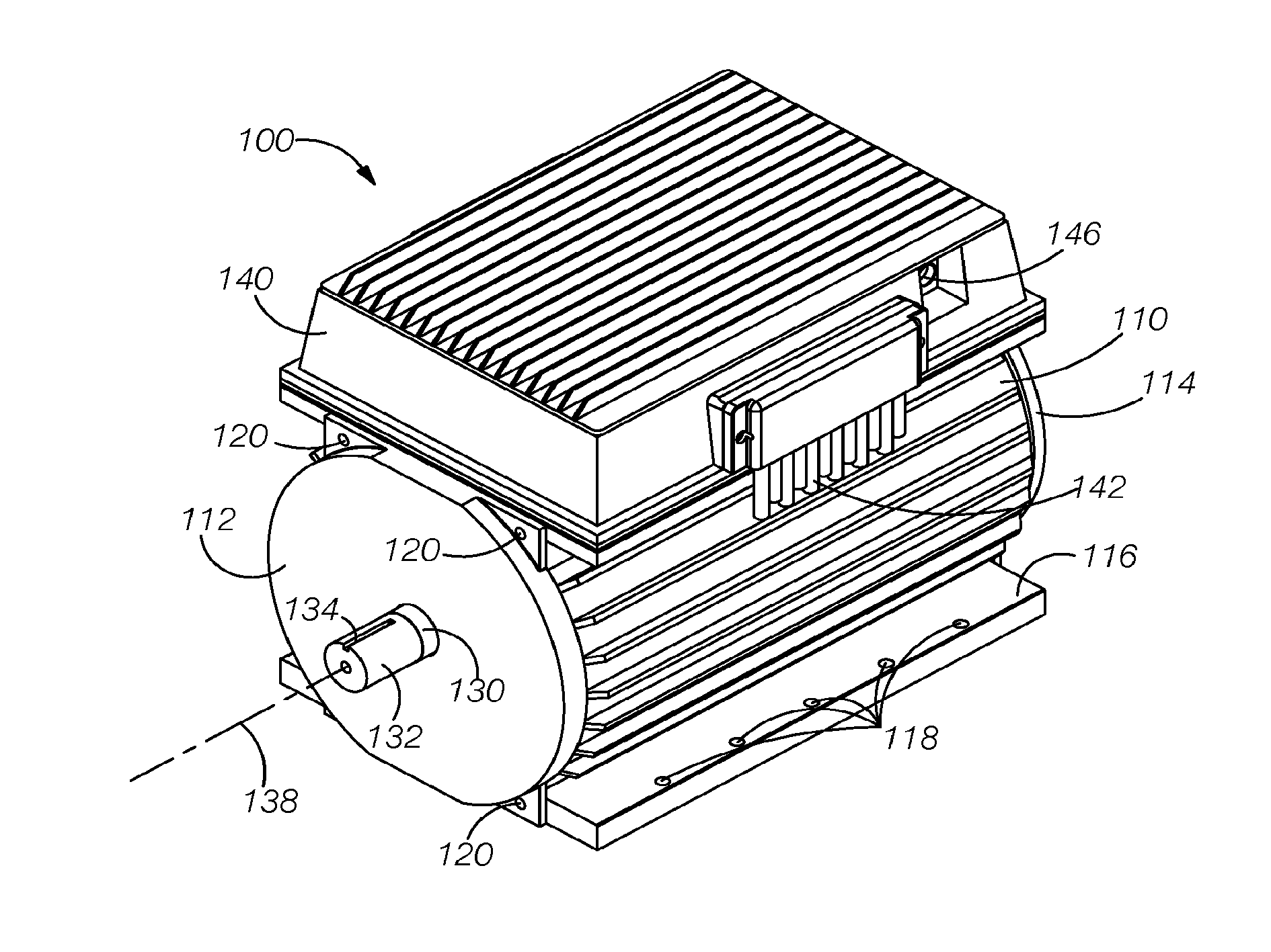
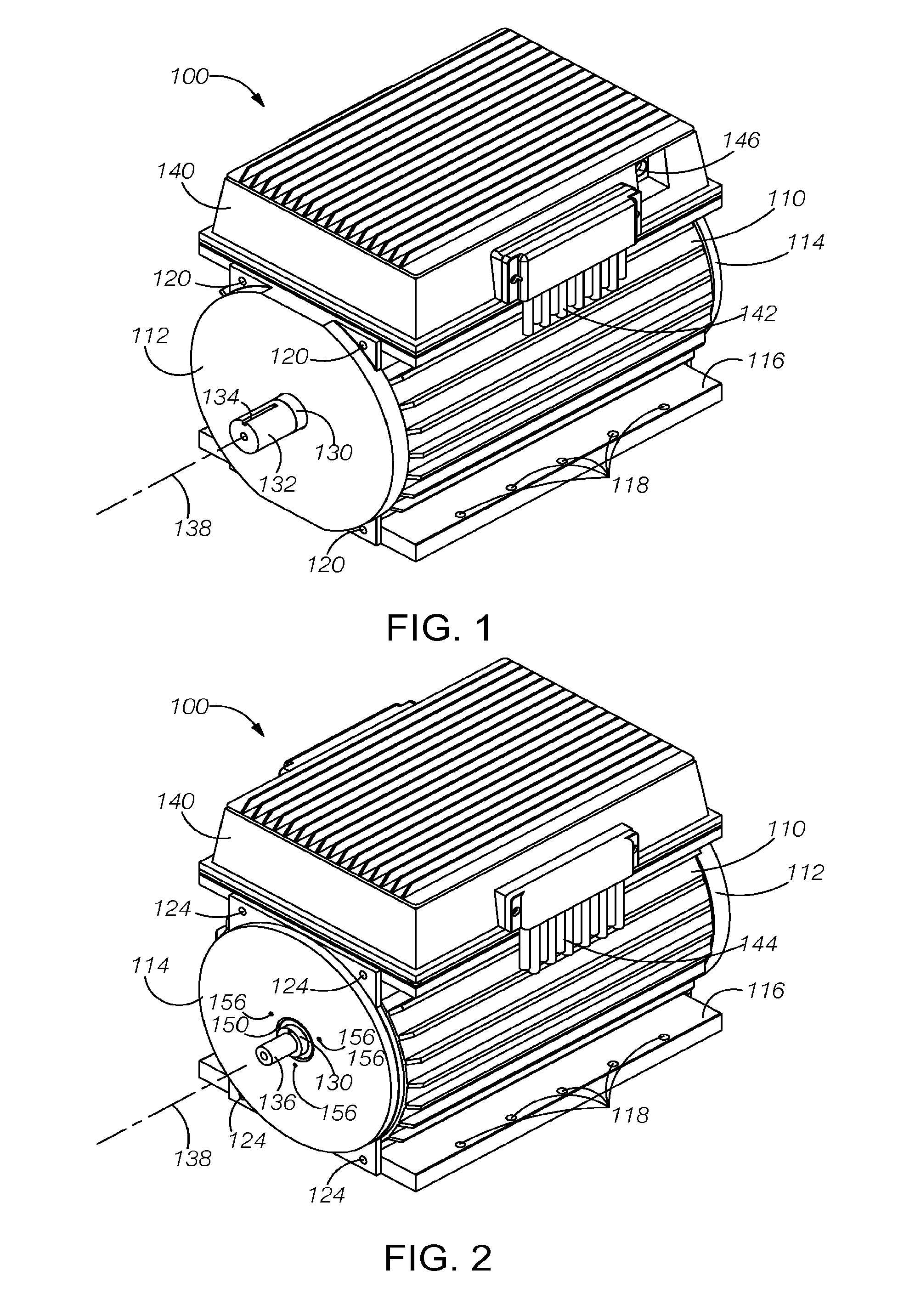
[0076]FIGS. 1 and 2 illustrate a front perspective view and a rear perspective view, respectively, of a brushless DC (BLDG) electric motor 100 constructed in accordance with the improvements disclosed herein. The motor includes an outer enclosure 110 having a front cover 112 and a rear cover 114. The outer enclosure further includes a mounting pedestal 116, which includes a plurality of mounting features 118 (e.g., bores) so that the motor can be secured to a watercraft (not shown).

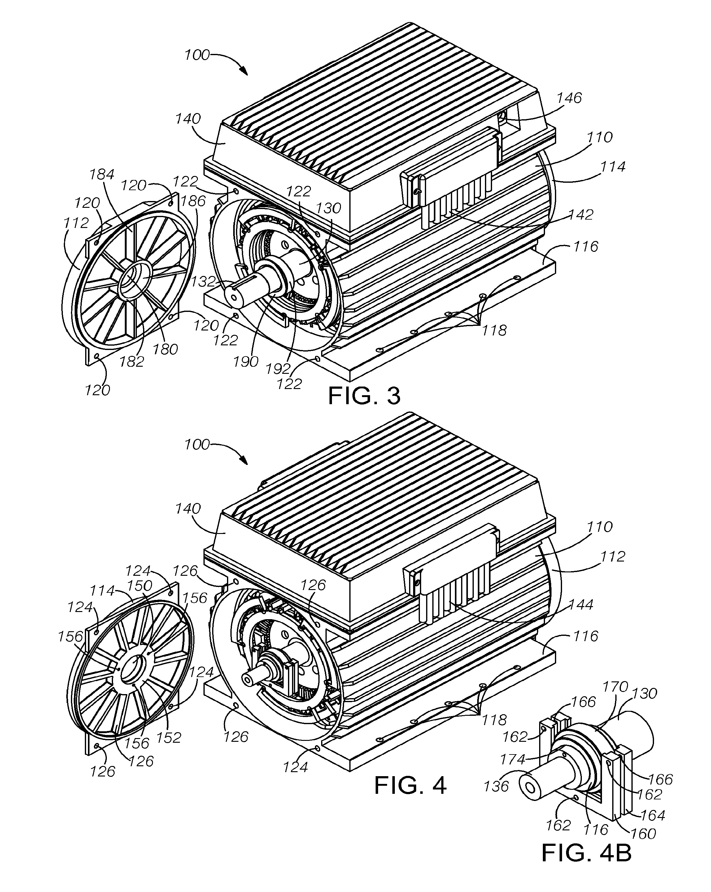
[0077]The front cover 112 is secured to the outer enclosure 110 by a plurality of threaded fasteners (not shown) that pass through unthreaded bores 120 in the front cover and engage threaded bores 122 on the front of the enclosure (see FIG. 3). The rear cover 114 is secu...


PUM


Abstract

A multi-phase, permanent magnet brushless DC electric motor includes 24 phase windings operating at a reduced voltage so that the motor can be powered by batteries or other sources of DC voltage to enable the motor to be used safely for propelling watercraft or other vehicles where the higher voltages required for conventional high horsepower motors would not be acceptable. The motor is wound by solid conductors spaced apart by 7.5 degrees. The conductors are interconnected and electrically driven by a sequence of drive currents to provide a six-pole stator. The connections to and interconnections between the stator windings are mirrored at each end of the stator to distribute the connections and interconnections between the two ends of the motor. A corresponding six-pole rotor using permanent magnets secured to a hollow rotor core is caused to rotate by the fields generated by the stator.

Description

BACKGROUND OF THE INVENTION[0001]1. Field of the Invention[0002]The present invention is in the field of electric motors, and, more particularly, is in the field of brushless DC electric motors for use in propelling vehicles such as watercraft.[0003]2. Description of the Related Art[0004]The need for the motor development described here comes from events that started a century ago when recreation size boats were propelled by electric motors. Eventually, such boats were converted to steam propulsion and then to propulsion by internal combustion engines. Except for small, slow-moving sightseeing boats and other limited horsepower boats, electric power is generally not used for recreational boats. Any trend towards the use of electric propulsion is generally stifled because of the inadequacies of the available batteries, which limits uses to low power, short duration applications.[0005]Today, the economics of gas and diesel fuel and the atmospheric degradation caused by internal combus...

Claims


Application Information

Patent Timeline
IPC IPC(8): H02K11/00
CPCH02K1/278H02K3/28H02K3/50H02K5/225H02K11/0073H02K1/185H02K9/14H02K2203/09H02K11/33
Inventor FERRAN, ROBERT J.
Owner FERRAN ROBERT J
Why Eureka
Try Eureka