Fluid transfer devices with sealing arrangement

a technology of fluid transfer device and sealing arrangement, which is applied in the field of fluid transfer device, can solve the problems of initial inaccurate alignment, leakage of liquid contents, and tear of liquid drug reconstitution fluid, and achieve the effect of being ready to apply

Active Publication Date: 2013-12-17
WEST PHARM SERVICES IL LTD
View PDF581 Cites 119 Cited by
  • Summary
  • Abstract
  • Description
  • Claims
  • Application Information

AI Technical Summary

Benefits of technology

[0007]The present invention is directed toward fluid transfer devices with a sealing arrangement for preventing leakage from medicament containing medicinal vessels or vials. The fluid transfer devices include a vial adapter having a top wall, a downward depending skirt with flex members for snap fitting onto a vial having a vial stopper, a pointed tubular cannula for piercing the vial stopper while snap fitting the vial adapter onto the vial, and a flow channel in flow communication with the cannula for enabling external flow communication with the vial interior. The vial adapter can have a general cylindrical shape skirt or a so-called flared skirt for assisting in guidance onto a vial.
[0009]The initial location of a sealing element along a cannula depends on whether a sealing element is intended to prevent negative pressure leakage or liquid leakage. In the former instance, a sealing element is necessarily disposed along a cannula towards its cannula tip such that it contacts a vial stopper prior to stopper perforation. In the latter instance, a sealing element may be disposed further from a cannula tip. Fluid transfer devices with proportionally sized sealing elements can be designed for use with different standard sizes of vials, for example, 13 mm, 20 mm, and larger. The present invention can be readily applied to conventional fluid transfer devices including a vial adapter with a pointed cannula.

Problems solved by technology

Tears may be formed in a vial stopper during snap fitting of a fluid transfer device thereonto leading to leakage of liquid contents during injection into and aspiration from the vial.
Tears also complicate liquid drug reconstitution in fluid transfer assemblages, for example, the aforesaid MIX2VIAL® fluid transfer assemblage, assisted by a negative pressure of a powder containing vial.
Tears often result from an initial inaccurate alignment between a fluid transfer device and a vial due to the latter centering the former as it snap fits thereonto such that the fluid transfer device is concentrically snap fit mounted onto the vial.
But tears may still occur even in the case of an initial concentric alignment between a fluid transfer device and a vial due to the constitution of an elastic vial stopper.

Method used


Image

  • Fluid transfer devices with sealing arrangement
  • Fluid transfer devices with sealing arrangement
  • Fluid transfer devices with sealing arrangement

Examples


Embodiment Construction

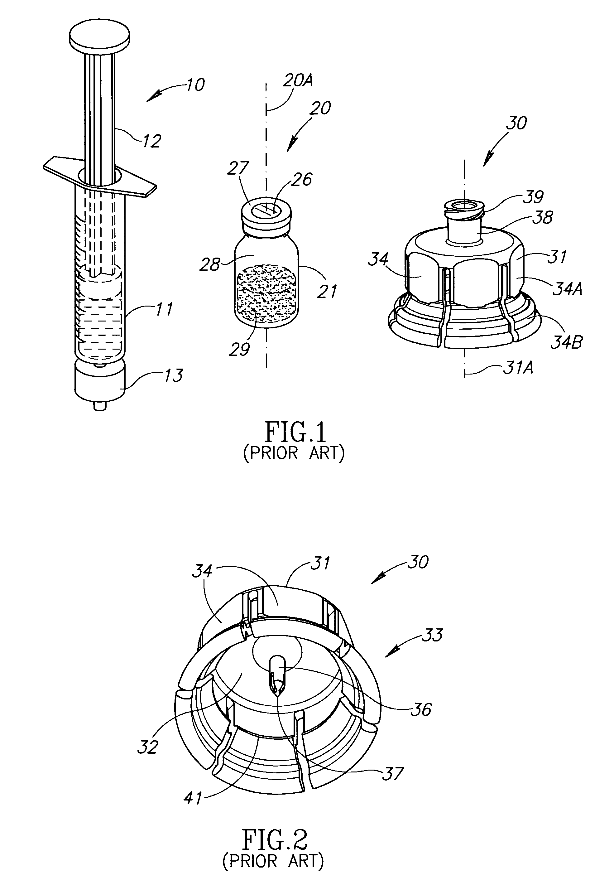
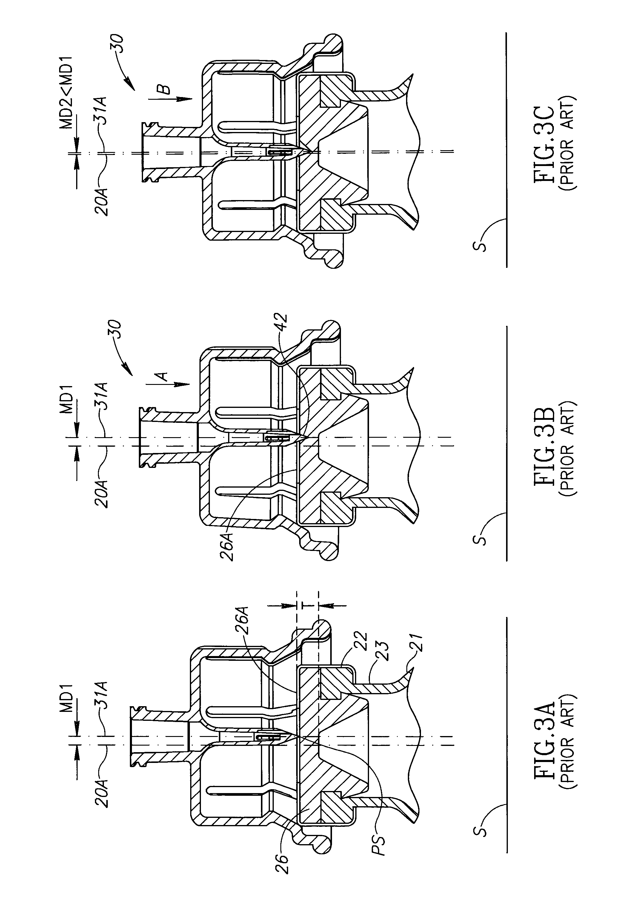
[0021]FIG. 1 shows a syringe 10 constituting a source of physiological fluid, a vial 20 constituting a medicinal vessel and a fluid transfer device 30 constituted by a female vial adapter for use with the syringe 10 and the vial 20, all as known in the art. The syringe 10 includes a barrel 11 with a plunger 12 and a male Luer lock connector 13. The syringe 10 can be formed with other types of male connectors. The vial 20 has a longitudinal vial axis 20A and includes a vial body 21 with a vial rim 22 and a narrow diameter neck 23 intermediate the vial body 21 and the vial rim 22. The vial rim 22 defines a vial opening 24 hermetically sealed by an elastic vial stopper 26, and capped by a metal band 27. The vial stopper 26 has a stopper thickness T adjacent the vial axis 20A. The vial body 21 defines a vial interior 28 containing either a powdered or liquid drug contents 29. The vial stopper 26 has an uppermost stopper surface 26A. The syringe 10 typically contains diluents for reconst...


PUM


Abstract

The present invention is directed toward fluid transfer devices including a vial adapter having a top wall and a cannula with a cannula tip, and an elastic O-ring like sealing element sealingly encircling the cannula and initially disposed towards the cannula tip and spaced apart from the top wall, the sealing element being brought into initial contact with the vial stopper subsequent to the cannula tip contacting the vial stopper at a puncture site and thereafter being slidingly urged towards the top wall and continuously sealing the puncture site during snap fit mounting the vial adapter on the vial.

Description

CROSS-REFERENCE TO RELATED APPLICATION[0001]This application is a Section 371 of International Application No. PCT / IL2010 / 000854, filed Oct. 19, 2010, which was published in the English language on May 19, 2011, under International Publication No. WO 2011 / 058545 A1, and the disclosure of which is incorporated herein by reference.FIELD OF THE INVENTION[0002]The invention relates to fluid transfer devices for use with medicinal vessels hermetically sealed by an elastic vial stopper and containing a liquid or powder medicament.BACKGROUND OF THE INVENTION[0003]Fluid transfer devices including a vial adapter with a pointed cannula for snap fitting on an aforesaid medicinal vessel or vial are now commonly employed for liquid drug reconstitution and administration purposes. Such devices include inter alia female vial adapters, male vial adapters, Applicant's MIXJECT® fluid transfer device, Applicant's MIX2VIAL® fluid transfer assemblage, and the like. Tears may be formed in a vial stopper ...

Claims


Application Information

Patent Timeline
Patent Type & Authority Patents(United States)
IPC IPC(8): A61B19/00
CPCA61J1/2096A61J2001/201A61J2001/2055A61J1/201A61J1/2055
Inventor LEV, NIMRODBEN SHALOM, NIV
Owner WEST PHARM SERVICES IL LTD
Why Eureka
Try Eureka