
Method for inscribing or marking surfaces

a marking or inscribed surface technology, applied in the field of can solve the problems of metallurgical changes in microstructure, affecting the effect of surface marking or inscribed, affecting the effect of surface marking, etc., and achieves the effect of avoiding disadvantages or avoiding disadvantages, and extremely smooth marking or inscribed surfa

Inactive Publication Date: 2013-12-17
TESA SE
View PDF16 Cites 0 Cited by
  • Summary
  • Abstract
  • Description
  • Claims
  • Application Information

AI Technical Summary

Benefits of technology

The invention provides a way to mark or inscribe metal surfaces that avoids the roughness of previous methods. After a high-energy beam is applied, the surface can be cleaned to remove any residues or absorption promoters that may not be needed. This results in a much smoother surface.

Problems solved by technology

In this operation, when the laser light is employed on the direct surface of the metal, there is a disadvantageous surface effect, since the laser light is coupled in directly on the surface and as a consequence in the zone of heat influence, there are burrs, furrows, melting events and metallurgical changes in microstructure.
A surface layer is consequently roughened and / or its microstructure altered, and so, for example, there may even be instances of weakening of the material.
This may be disadvantageous in particular in the case of certain fields of application, as for example in medical engineering or else in other fields of application where the desire is for particularly smooth or clean marked surfaces.

Method used


Image

  • Method for inscribing or marking surfaces
  • Method for inscribing or marking surfaces
  • Method for inscribing or marking surfaces

Examples


Embodiment Construction

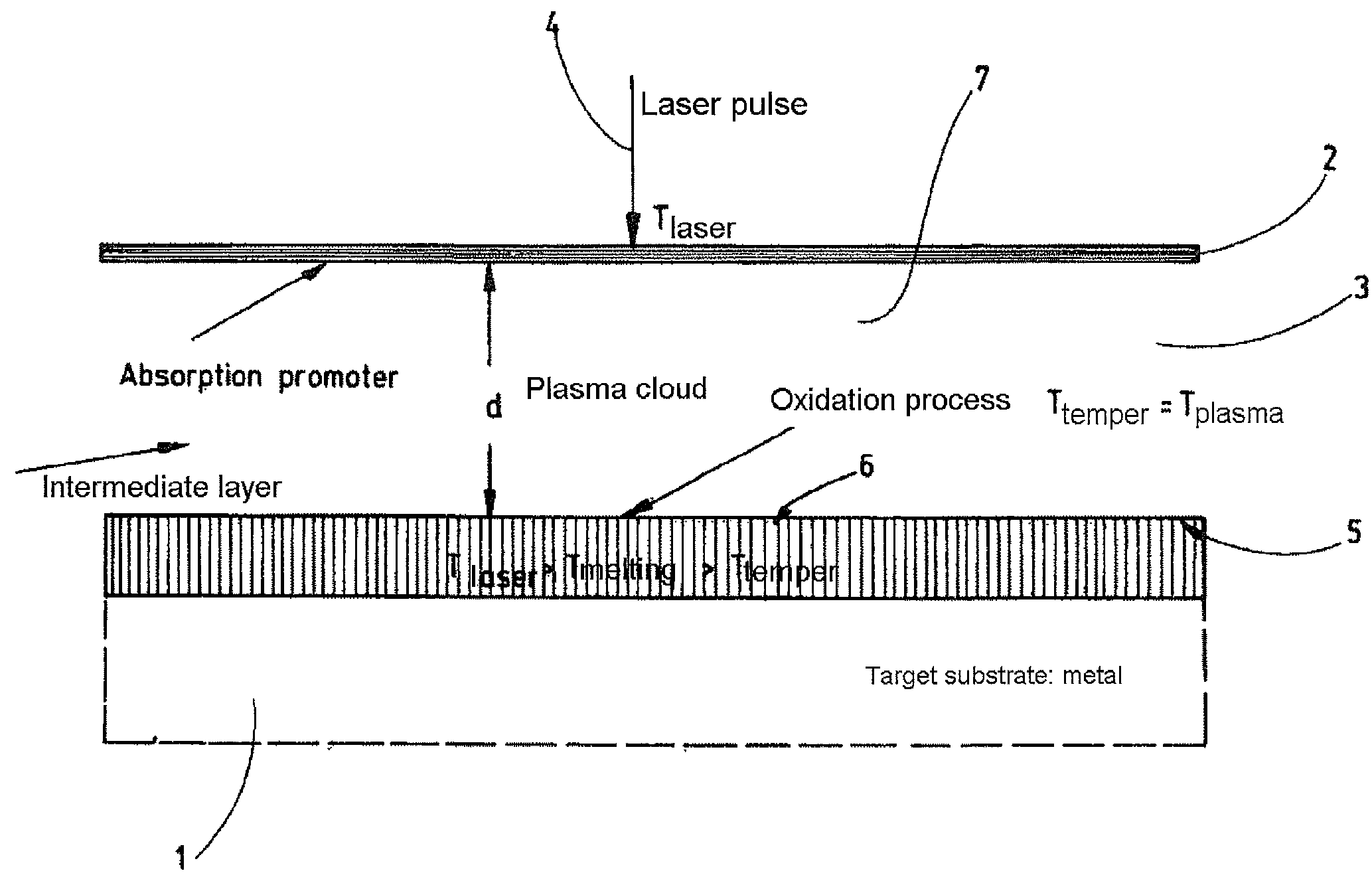
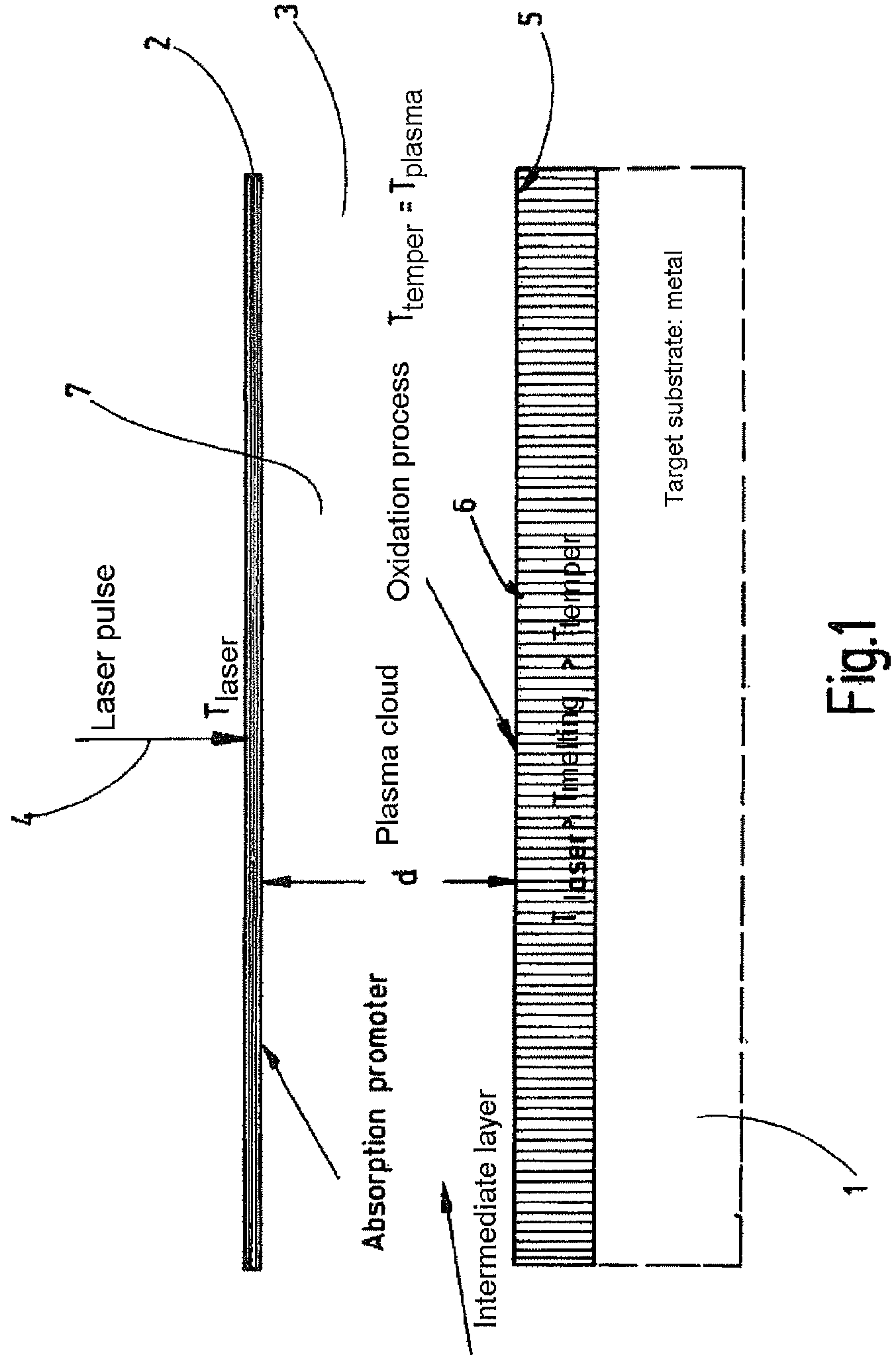
[0020]FIG. 1 shows diagrammatically a metal surface which is to be marked or inscribed. For that purpose a layer 2 is applied to the metal surface, the layer being composed of what is called an absorption promoter. The layer is advantageously at a distance d from the metal surface. When high-energy radiation, such as laser radiation 4, in the form for example of a laser pulse, is irradiated, the radiation or the laser light is not brought directly into contact or interaction with the metal surface, but instead, as a result of the impingement of the laser light on the layer of absorption promoter 2, the laser light is converted into heat, which acts on the metal surface 1. The absorption promoter, through absorption of the laser light, is converted locally into a plasma 3, also called plasma cloud, and the plasma 3 delivers the heat to the adjacent metal, at which point, locally, heating takes place until the tempering temperature is reached. The distance d between the absorption pro...


PUM

PropertyMeasurementUnit
Lengthaaaaaaaaaa

Abstract

Disclosed is a method for inscribing or marking surfaces (1), especially metal surfaces. In said method, the surface (1) that is to be inscribed or marked is coated with an absorption promoter (2) in a first step, whereupon a high-energy beam (4), e.g. a laser beam, which colors the surface (1) as a result of the interaction with the absorption promoter by means of a temperature increase, is applied to surface elements that re to be inscribed or colored.

Description

[0001]This is an application filed under 35 USC §371 of PCT / EP2008 / 051292, claiming priority to DE 10 2007 008 668.9 filed on Feb. 20, 2007.BACKGROUND OF THE INVENTION[0002]The invention relates to a method of marking or inscribing surfaces, more particularly surfaces of metals.[0003]With metals there are a variety of marking methods known. For example a marking may be produced by means of application of material, such as with ink, or else with depletion of material, such as in the case of engraving.[0004]It is also possible to perform what is referred to as temper marking or else oxidation marking. This means that the metal at its surface undergoes changes in color in certain areas as a result of selective temperature change. In the case of metals which are heated to a predeterminable temperature, oxidation processes on the surface give the surface a colored appearance and hence a colored coloration, inscription or marking. In this case it is possible to influence the thickness of ...

Claims


Application Information

Patent Timeline
IPC IPC(8): H05H1/24
CPCB41M5/262
Inventor KOOPS, ARNEREITER, SVENARAI, NORIO
Owner TESA SE
Learn More