
Image capturing apparatus

a technology of image capturing and capturing apparatus, which is applied in the direction of printers, cameras, instruments, etc., can solve the problems of reducing the detection performance of focus, affecting the accuracy of image capturing, so as to achieve high image quality and high precision focus detection performance.

Active Publication Date: 2013-12-17
CANON KK
View PDF9 Cites 5 Cited by
  • Summary
  • Abstract
  • Description
  • Claims
  • Application Information

AI Technical Summary

Benefits of technology

The present invention aims to solve the problems of focus detection in image sensors by providing both high-precision focus detection and high image quality. By disposing focus detection pixels on the image sensor, the invention enables effective detection of focus in captured images.

Problems solved by technology

Here, if the focus detection pixels are disposed at a sparse density, image quality degradation due to the above-described pixel defect can be alleviated, but on the other hand, focus detection image sampling characteristics deteriorate, resulting in a decrease in focus detection performance.
However, the above-described known techniques suffer the following problems.
Moreover, disposing the focus detection pixels densely imposes a limitation on neighboring image forming pixel options that can be referred to in performing an interpolation operation, and thus makes it highly probable that the correction error will increase.

Method used


Image

  • Image capturing apparatus
  • Image capturing apparatus
  • Image capturing apparatus

Examples


Embodiment Construction

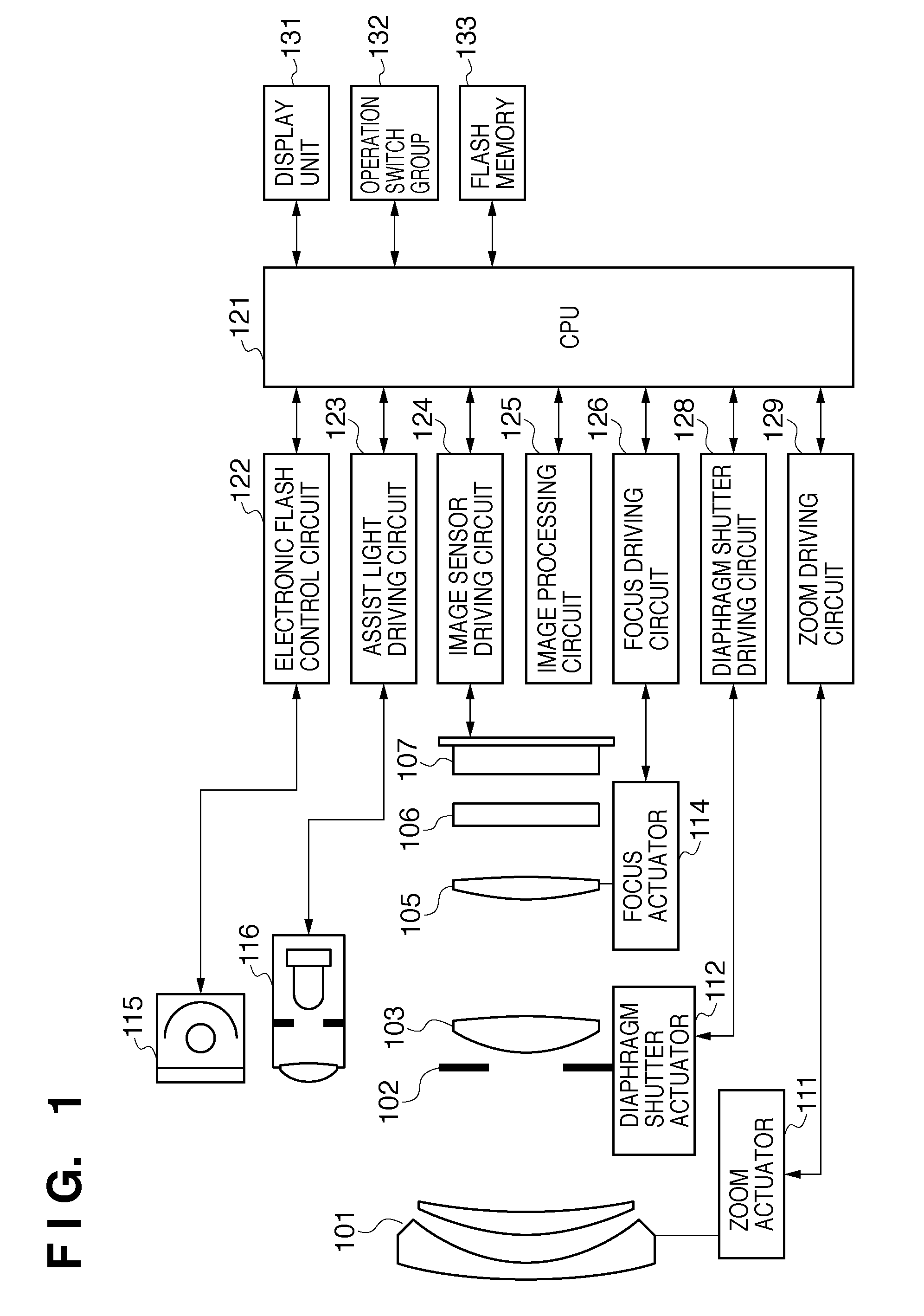
[0023]FIG. 1 is a diagram showing the configuration of a camera according to an embodiment of the present invention and shows an electronic camera in which a camera main body including an image sensor and an imaging lens are integrated into a single unit. In FIG. 1, reference numeral 101 denotes a first lens group disposed at a front end of an imaging optical system (image forming optical system), held so as to be movable forward and backward in an optical axis direction. Reference numeral 102 denotes a diaphragm shutter, which adjusts the amount of light during shooting by controlling the aperture diameter thereof and also has the function of a shutter for controlling the exposure time during shooting of a still image. Reference numeral 103 denotes a second lens group. The diaphragm shutter 102 and the second lens group 103 move together forward and backward in the optical axis direction, and by moving in conjunction with forward and backward movement of the first lens group 101, p...


PUM


Abstract

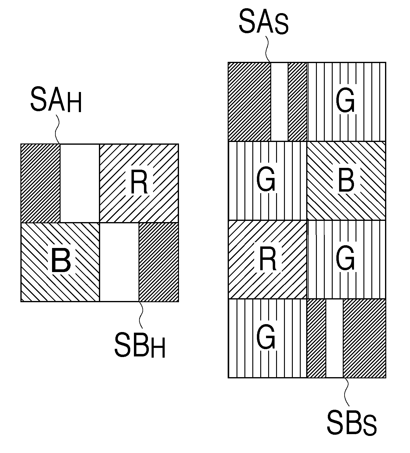
An image capturing apparatus includes an image sensor having a focus detection pixel group including a plurality of focus detection pixels that receive light passing through a part of a pupil area of an imaging lens for forming an object image and an image forming pixel group including a plurality of image forming pixels that receive light passing through the whole of the pupil area of the imaging lens; and an image processing unit that generates an image signal corresponding to the position of each of the focus detection pixels by using at least either of a signal of the focus detection pixel at the position and signals of neighboring image forming pixels of the focus detection pixel at the position, depending on the size of an aperture of the focus detection pixels.

Description

BACKGROUND OF THE INVENTION[0001]1. Field of the Invention[0002]The present invention relates to an image capturing apparatus such as a digital camera or a video camera, and particularly relates to an image capturing apparatus that performs focus detection based on the output from an image sensor.[0003]2. Description of the Related Art[0004]Technology for eliminating the need for a dedicated AF sensor and realizing high-speed phase difference AF on an image sensing plane by providing a phase difference detection function to an image sensor has been proposed. For example, according to Japanese Patent Laid-Open No. 2000-156823, in part of light receiving elements (pixels) on an image sensor, a sensitive area of a light receiving unit is positioned eccentrically with respect to an optical axis of an on-chip microlens, thereby providing a pupil division function. These pixels are used as focus detection pixels and disposed among a group of image forming pixels at predetermined intervals...

Claims


Application Information

Patent Timeline
Patent Type & Authority Patents(United States)
IPC IPC(8): G03B13/00H04N25/00
CPCG03B13/00
Inventor ISHII, HIROKAZU
Owner CANON KK
Learn More