
Low cost, active antenna arrays

a low-cost, active technology, applied in the field of active arrays, can solve the problems of high loss limiting system performance, and high cost of corporate feed and programmable phase shifters

Active Publication Date: 2013-12-17
NEC ADVANCED NETWORKS INC
View PDF8 Cites 32 Cited by
  • Summary
  • Abstract
  • Description
  • Claims
  • Application Information

AI Technical Summary

Benefits of technology

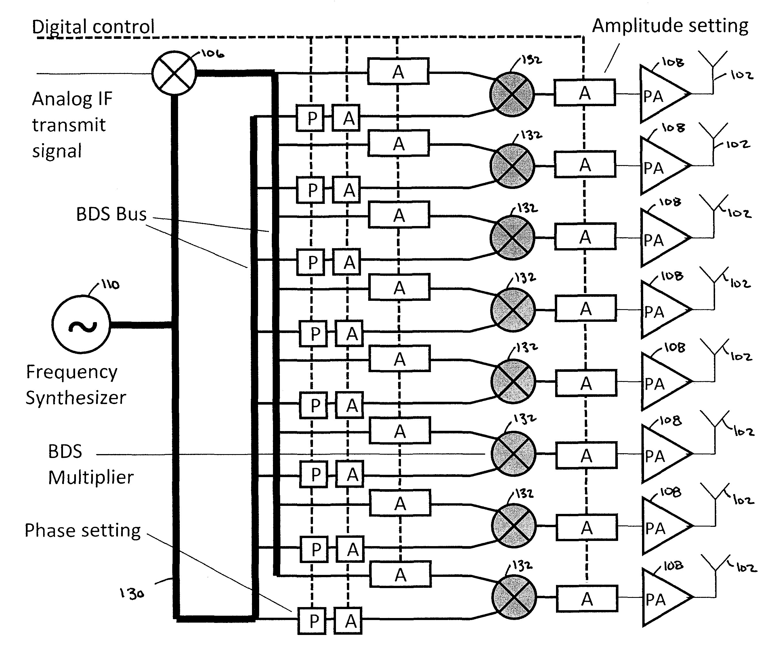
The present invention provides methods and systems for distribution and aggregation of signals in an active antenna array with amplitude and phase control at every antenna element. These methods and systems use a bidirectional signaling network called a BDS bus and local processing circuits called ATAA circuits. The ATAA circuits have the ability to change the amplitude and phase of signals under electronic control. The invention also includes a transmitter circuit with a BDS bus, TAPA circuits, mixer circuits, A-Setting circuits, and antennas. The invention also provides a receiver circuit with a BDS bus, TAPA circuits, mixer circuits, A-Setting circuits, and antennas. The technical effects of the invention include improved signal distribution, improved signal-to-noise ratio, improved phase control, and improved amplitude control.

Problems solved by technology

These components have high loss limiting the system performance.
For both PESA and EISA, the corporate feed and the programmable phase shifters are high performance expensive components.
The practical realization of the corporate feed is expensive because this network contains many signal splitting / combining operations and because the transmission line sections must be accurately matched in length and terminated electrically with accurate impedances.
All these design conditions are error prone.
First, the hardware of these systems is naturally expensive since there are many (4-12) radio systems present.
Second, the software generating the signals is extensive and runs in real time, requiring substantial processing power.
Third, having only 12 or less antennas per system limits the array performance.
In principle, the number of antennas in software-configured digital arrays can be scaled with a corresponding increase in system cost and size.

Method used


Image

  • Low cost, active antenna arrays
  • Low cost, active antenna arrays
  • Low cost, active antenna arrays

Examples


Embodiment Construction

[0065]Before presenting detailed descriptions of various embodiments of the invention, it is useful to first understand the operation of the bidirectional signal distribution concept which will be used in those various embodiments.

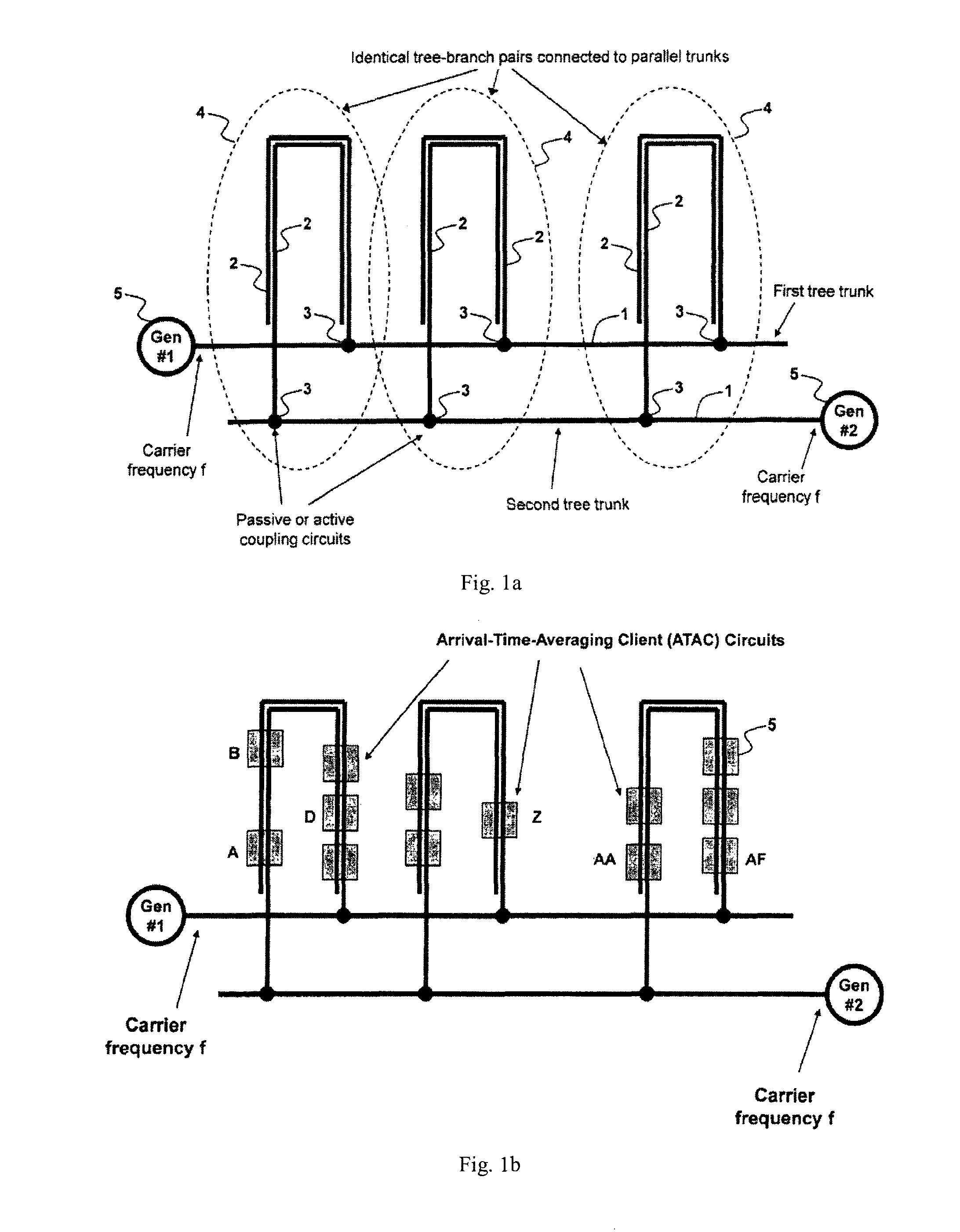
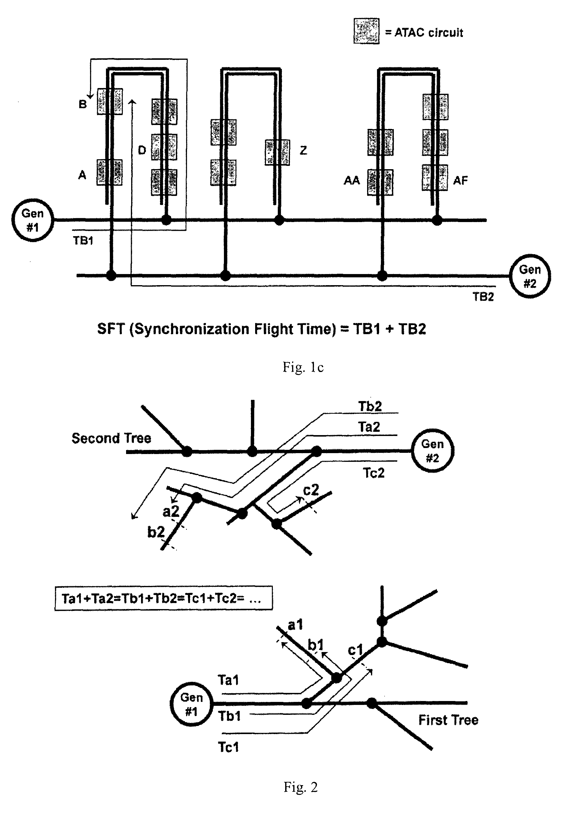
[0066]FIG. 1(a) depicts a schematic diagram of two independent tree networks, each consisting of a tree trunk 1 and tree branches 2. We will refer to this below generally as a BDS (bidirectional signaling) bus. The tree trunk and the tree branches of each of the tree networks are properly terminated signal transmission lines (termination circuits are not shown in FIG. 1(a) for simplicity), such as electrical microstrip lines, optical wave-guides, sound propagating guides, or simple electrical traces. The difference between trunk 1 and branches 2 is not in substance but rather in name, based on the relative position of the signal transmission lines (TL) with respect to the tree network input port. Trunk 1 is defined as the signal transmission line connected...


PUM


Abstract

A transmitter system including: a bidirectional signaling (BDS) network having first and second networks for carrying first and second carrier signals, and having a set of n phase synchronous location pairs (ai, bi); and also including tunable transmitter circuits for driving an antenna array, each tunable transmitter circuit having an output line for carrying an output signal and first and second input lines electrically connected to the first and second networks of the BDS network at locations of a corresponding one of the set of phase synchronous location pairs, and including a multiplier having a first input electrically connected to the first input line of that tunable transmitter circuit; a phase setting circuit electrically connected to the multiplier for controlling the phase of the output signal of that tunable transmitter circuit; and an amplitude setting circuit for controlling the amplitude of the output signal of that tunable transmitter circuit.

Description

[0001]This application claims the benefit of U.S. Provisional Application No. 61 / 360,737, filed Jul. 1, 2010, all of which is incorporated herein by reference.TECHNICAL FIELD[0002]Embodiments of the present invention generally relate to active arrays such as phased arrays for smart antennas.BACKGROUND OF THE INVENTION[0003]Antenna arrays are used in applications such as radars and beam-based communication systems. For example, see R. Mailloux, “Phased Array Antenna Handbook,” 2nd edition, Artech House, 2005; D. Parker and D. Zimmermann, “Phased Arrays-Part I: Theory and Architectures,” IEEE Trans. Microwave Theory and Techniques, vol. 50, March 2002; D. Parker and D. Zimmermann, “Phased Arrays-Part II: Implementations, Applications, and Future Trends,” IEEE Trans. Microwave Theory and Techniques, vol. 50, March 2002. The main reason for using antenna arrays is their capability of generating special dynamic radiation patterns such as steerable beams without any mechanical movement.[0...

Claims


Application Information

Patent Timeline
Patent Type & Authority Patents(United States)
IPC IPC(8): H04M1/00H04B1/04
CPCH01Q3/26H04B7/0682
Inventor BANU, MIHAIFENG, YIPINGPRODANOV, VLADIMIR I.
Owner NEC ADVANCED NETWORKS INC
Learn More