Multifunctional extruding press with multiple equipment and extrusion method thereof

a multi-functional, extruding press technology, applied in the direction of presses, metal extrusion, manufacturing tools, etc., can solve the problems of complicated movement system of shears, large size, and complicated operation

Inactive Publication Date: 2013-12-24
DANIELI & C OFF MEC SPA
View PDF7 Cites 2 Cited by
  • Summary
  • Abstract
  • Description
  • Claims
  • Application Information

AI Technical Summary

Benefits of technology

[0096]In particular, the machining dead times are reduced with consequent increase of production time and simplification of the extrusion process, and the manufacturing complexity of the press is reduced.
[0097]A further important advantage is the energy saving allowed by the possibility of a smaller dimensioning of the power both installed and consumed by the press. Indeed, the working speed of the extrusion presses depends on the type of metal to be extruded and is mainly determined by two factors: the installed maximum hydraulic capacity and the diameter of the moving control cylinders. This also affects the dimensioning of the hydraulic pumps.
[0102]From the description above, a person skilled in the art will be able to implement the object of the invention without introducing further constructional details.

Problems solved by technology

In order to extract the billet loader, before closing the container, the billet is supported by the pressing shank which pushes it against the matrix (this is a very delicate operation).
These types of known presses have major problems related to excessively long dead times needed to replace the billets to be extruded and shear the bases: each billet replacement may require a time ranging from 15 to 30 seconds, and there is no active working during this time.
Considering that these presses work in a continuous cycle, the dead times negatively and severely affect the machine productivity.
A further important problem is related to the movement system of the shears which is complicated and large in size.

Method used


Image

  • Multifunctional extruding press with multiple equipment and extrusion method thereof
  • Multifunctional extruding press with multiple equipment and extrusion method thereof
  • Multifunctional extruding press with multiple equipment and extrusion method thereof

Examples


Embodiment Construction

[0040]The multifunctional extruding press with multiple equipment object of the invention will now be described with reference to the accompanying figures.

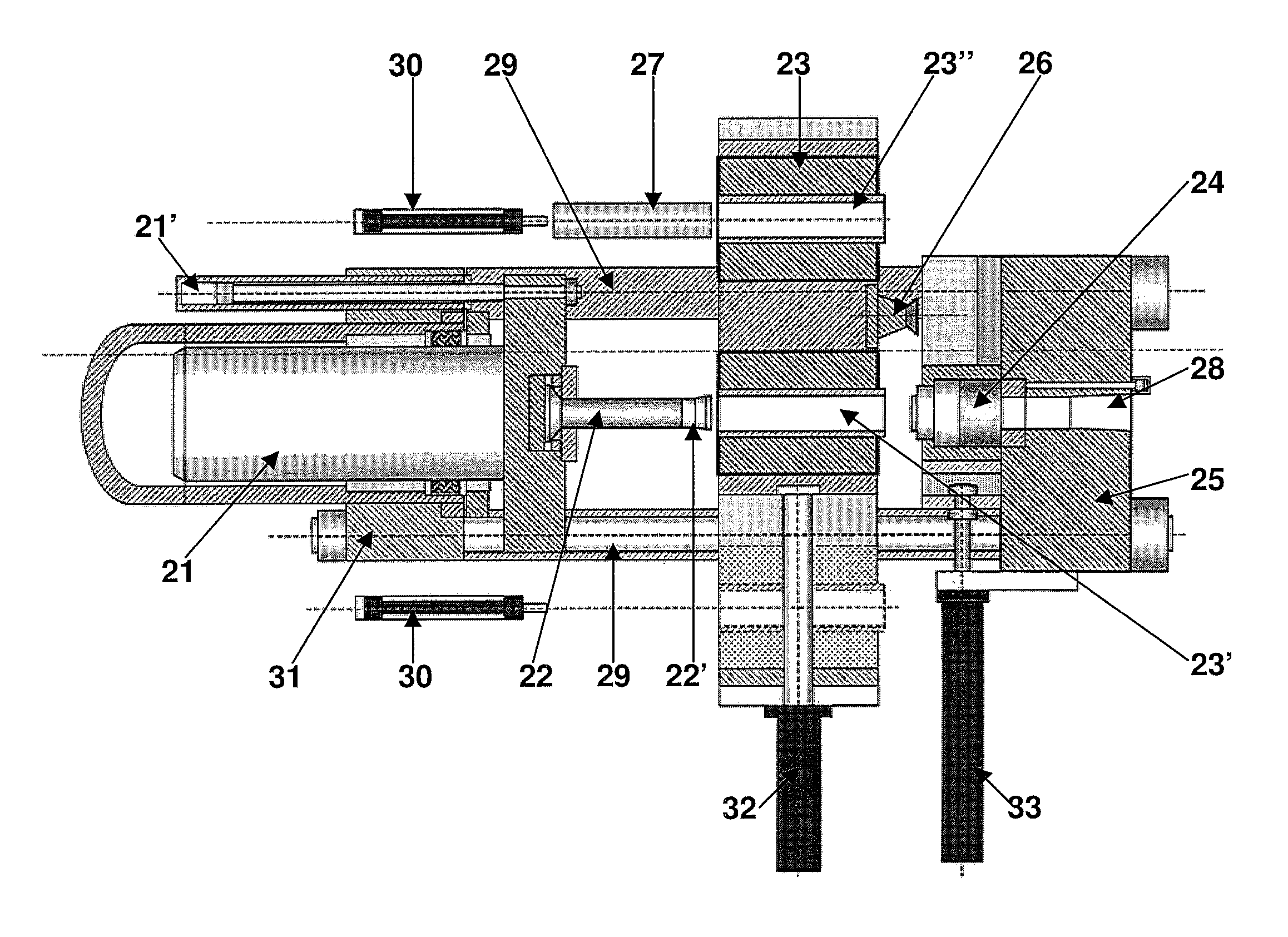
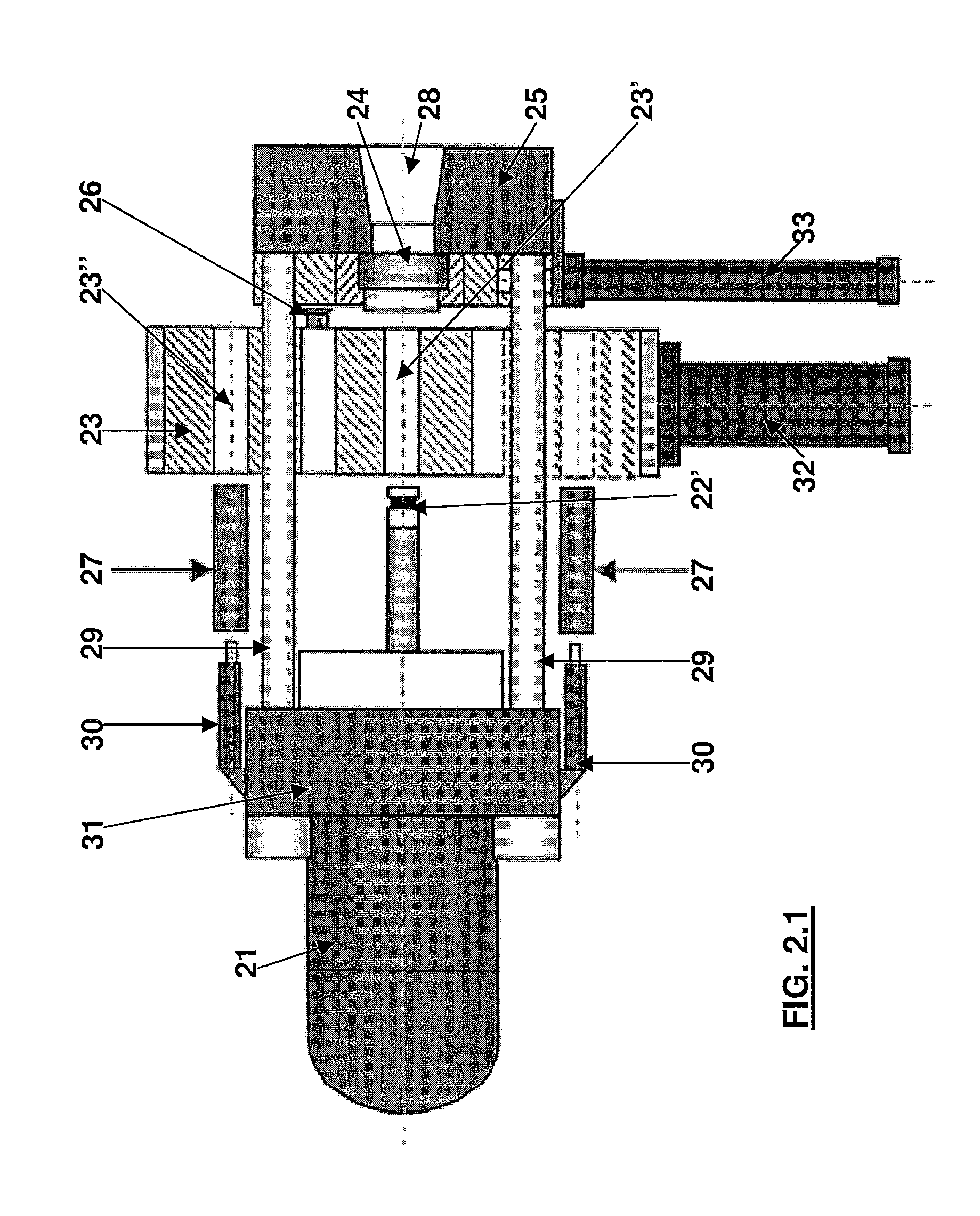
[0041]With particular reference to FIGS. 2.1, 2.2, numeral 21 indicates a main cylinder of per se known type.

[0042]Numeral 22 indicates a pressing shank with corresponding pressing heel 22′ of per se known type.

[0043]Numeral 25 indicates a die platen element in which there is provided a hole 28 known per se, in which the matrix 24 is present on the inner side thereof. The matrix may be laterally moved by means of an appropriate cylinder 33.

[0044]In accordance with the invention, a multiple equipment assembly 23 is provided, consisting of a cross element 35 and a ram or slide 36 equipped with a plurality of containers for accommodating the billets 27. Two containers 23′, 23″ are shown in the figures, but this is not to be intended as a limitation because more than two containers are also possible. The containers may be moved transv...


PUM

PropertyMeasurementUnit
diametersaaaaaaaaaa
diametersaaaaaaaaaa
temperaturesaaaaaaaaaa

Abstract

An extruding press comprising: a die platen element (25) with an extrusion matrix (24) from which an extruded product comes out; a main cylinder (21); longitudinal columns (29) connecting the die platen element (25) to the main cylinder (21); a multiple equipment provided with at least two containers (23′, 23″) for housing the billets, and comprising an external, longitudinally moving, cross element and a transversally moving ram inside said cross element which comprises the containers; means for longitudinally moving the cross element and means for transversally moving the internal ram to make one of the containers (23′, 23″) face the extrusion matrix (24) and make one or more of the other containers be in front of the billet introducing means (30) at the same time as said extrusion of the billet.

Description

FIELD OF THE INVENTION[0001]The present invention relates to a multifunctional extruding press with multiple equipment and to an extrusion method thereof.STATE OF THE ART[0002]With reference to FIG. 1.1, the extruding presses of known type essentially comprise the following components.[0003]There is a main cylinder 1 with the task of providing the thrust or force for deforming a billet 7.[0004]The billet 7 is the starting product for the extrusion process, and may be made of various metals or alloys (aluminum, copper, brass, steel, etc.) and may have various diameters.[0005]The thrust of the main cylinder 1 is proportioned to the type of metal being machined (typically aluminum, copper, brass, steel) and to the diameter of the billet. The currently marketed presses develop extrusion forces from 1000 to 10000 tons (and more), while the diameters of the billets may be in the range from 127 mm (5″) to 610 mm (24″).[0006]Each metal has a specific working pressure under which extrusion i...

Claims


Application Information

Patent Timeline
Patent Type & Authority Patents(United States)
IPC IPC(8): B21C27/00B21C33/00
CPCB21C23/214B21C27/00B21C33/00B21C35/04
Inventor DEPLANO, STEFANOMAGNOLI, UMBERTOBORGONOVO, MAURIZIO
Owner DANIELI & C OFF MEC SPA
Why Eureka
Try Eureka