Composite metal-polymer bushing and crankshaft assembly

a technology of metal-polymer bushings and crankshafts, which is applied in the field of compressors, can solve the problems of excessive wear and/or galling of the bushings, reduce the usable life of the bushings, etc., and achieve the effect of reducing the wear rate of the bushings

Active Publication Date: 2013-12-24
TRANE INT INC
View PDF27 Cites 7 Cited by
  • Summary
  • Abstract
  • Description
  • Claims
  • Application Information

AI Technical Summary

Benefits of technology

[0003]The present invention provides, in one aspect, an assembly including a composite metal-polymer bushing having an outer metal layer with an inner surface, metal particles sintered to the inner surface, a polymer material between the metal particles, a finished interior surface collectively defined by the polymer material and exposed portions of the metal particles, a plurality of interstices formed between the metal particles and the polymer material, and a plurality of ridges defined by the polymer material that protrude above the metal particles. The ridges occupy at least about 8% of the area of a cylindrical reference surface nominally coinciding with the finished interior surface. The assembly also includes a crankshaft having a journal at least partially received within the bushing and supported by the finished interior surface. The journal is polished to a surface finish of about 0.1 microns or less to reduce a wear rate of the bushing.

Problems solved by technology

Consequently, undesirably high frictional forces may develop between the crankshaft and the bushings, potentially causing excess wear and / or galling of the bushing, and possibly reducing the usable life of the bushing.

Method used


Image

  • Composite metal-polymer bushing and crankshaft assembly
  • Composite metal-polymer bushing and crankshaft assembly
  • Composite metal-polymer bushing and crankshaft assembly

Examples


Embodiment Construction

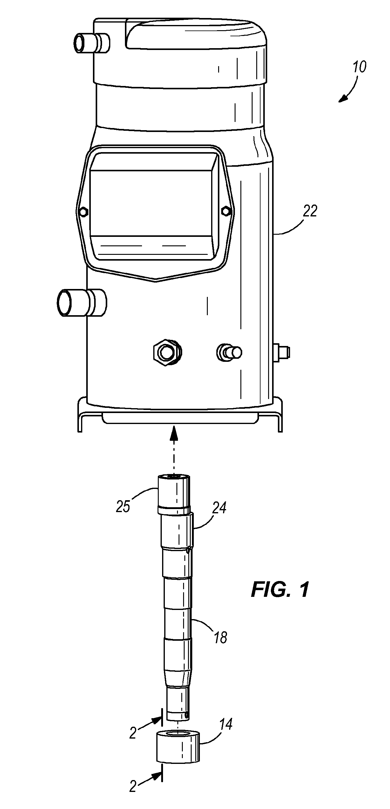
[0015]FIG. 1 illustrates an assembly 10 including a composite metal-polymer bushing 14, a crankshaft 18, and a compressor 22 in which the bushing 14 and the crankshaft 18 are incorporated. The crankshaft includes at least one journal 24 that is received within and rotatably supported by the bushing 14. The compressor 22 is configured as a hermetic refrigerant scroll compressor 22 including a movable scroll (not shown) driven in an orbiting manner by an eccentric 25 on the crankshaft 18 relative to a fixed scroll (also not shown). In addition to the bushing 14 being positioned on the journal 24, a substantially identical bushing (not shown) may be positioned between the eccentric 25 and the movable scroll. Alternatively, the compressor 22 may be configured in any of a number of different ways for pumping refrigerant or any other substance.

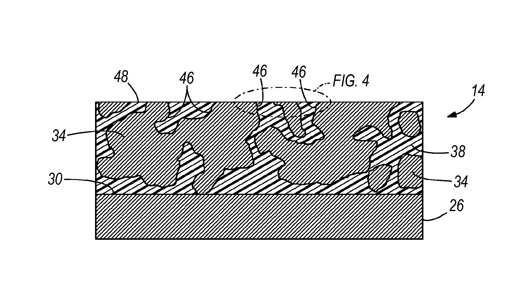
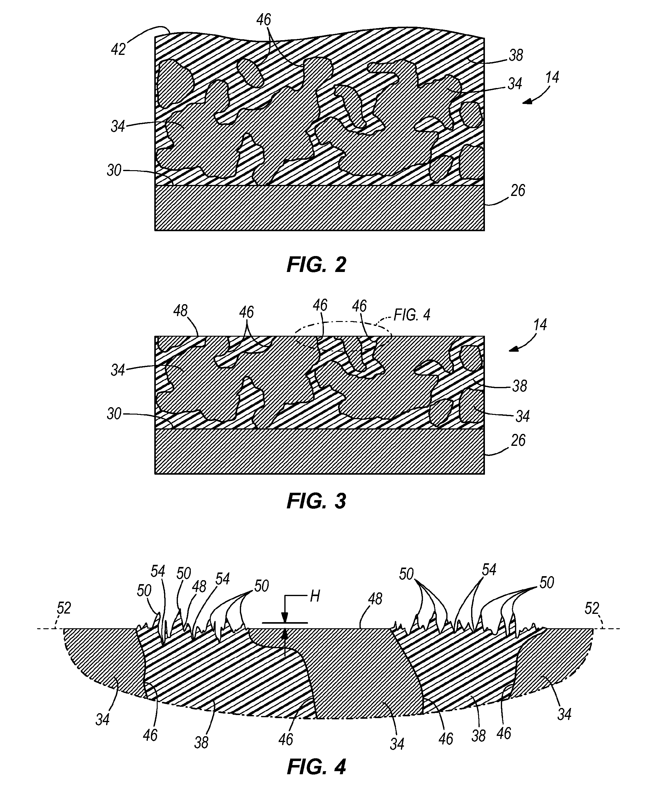
[0016]With reference to FIG. 2, the bushing 14 includes an outer metal layer 26 having an inner surface 30, metal particles 34 (e.g., bronze, alumi...


PUM

PropertyMeasurementUnit
heightaaaaaaaaaa
Raaaaaaaaaaa
areaaaaaaaaaaa

Abstract

An assembly includes a composite metal-polymer bushing having an outer metal layer with an inner surface, metal particles sintered to the inner surface, a polymer material between the metal particles, a finished interior surface collectively defined by the polymer material and exposed portions of the metal particles, a plurality of interstices formed between the metal particles and the polymer material, and a plurality of ridges defined by the polymer material that protrude above the metal particles. The ridges occupy at least about 8% of the area of a cylindrical reference surface nominally coinciding with the finished interior surface. The assembly also includes a crankshaft having a journal at least partially received within the bushing and supported by the finished interior surface. The journal is polished to a surface finish of about 0.1 microns or less to reduce a wear rate of the bushing.

Description

FIELD OF THE INVENTION[0001]The present invention relates to compressors, and more particularly to bushing and crankshaft assemblies for use in compressors.BACKGROUND OF THE INVENTION[0002]Hermetic refrigerant scroll compressors include crankshafts typically rotatably supported by bushings. Following shut-down, the refrigerant in the scroll compressors can behave as a “degreaser” and remove residual lubricant situated on the crankshaft and / or bushings. Then, when re-starting the compressor, little or no residual lubricant may be available to the bushings and the crankshaft until additional lubricant is pumped to the bushings and the crankshaft. Consequently, undesirably high frictional forces may develop between the crankshaft and the bushings, potentially causing excess wear and / or galling of the bushing, and possibly reducing the usable life of the bushing.SUMMARY OF THE INVENTION[0003]The present invention provides, in one aspect, an assembly including a composite metal-polymer b...

Claims


Application Information

Patent Timeline
Patent Type & Authority Patents(United States)
IPC IPC(8): F16C9/02B21D53/00
CPCF04C23/008F16C33/24F04C18/0215F04C2230/92F04C2240/56F05C2225/04Y10T29/49668F05C2253/04Y10T74/2173Y10T29/17Y10T29/49236F05C2251/14F16C2360/42
Inventor BENCO, MICHAEL G.LAPP, WILLIAM E.LEPAK, DERRICK J.BUTTERWORTH, ARTHER L.JANDA, DAVIDDORMAN, DENNIS R.
Owner TRANE INT INC
Why Eureka
Try Eureka