In situ lysis of cells in lateral flow immunoassays

a technology of immunoassay and in situ lysis, which is applied in the field of lateral flow immunoassay, can solve the problems of too complex or time-consuming for practical operation in a clinical setting

Active Publication Date: 2013-12-24
RAPID PATHOGEN SCREENING INC
View PDF57 Cites 53 Cited by
  • Summary
  • Abstract
  • Description
  • Claims
  • Application Information

AI Technical Summary

Problems solved by technology

As an example, fever is a common cause of childhood visits to urgent care centers for both family practice and pediatric offices.
However, such an added lysis step may complicate and delay an assay, even causing it to be too complex or time consuming for practical operation in a clinical setting.

Method used


Image

  • In situ lysis of cells in lateral flow immunoassays
  • In situ lysis of cells in lateral flow immunoassays
  • In situ lysis of cells in lateral flow immunoassays

Examples


example

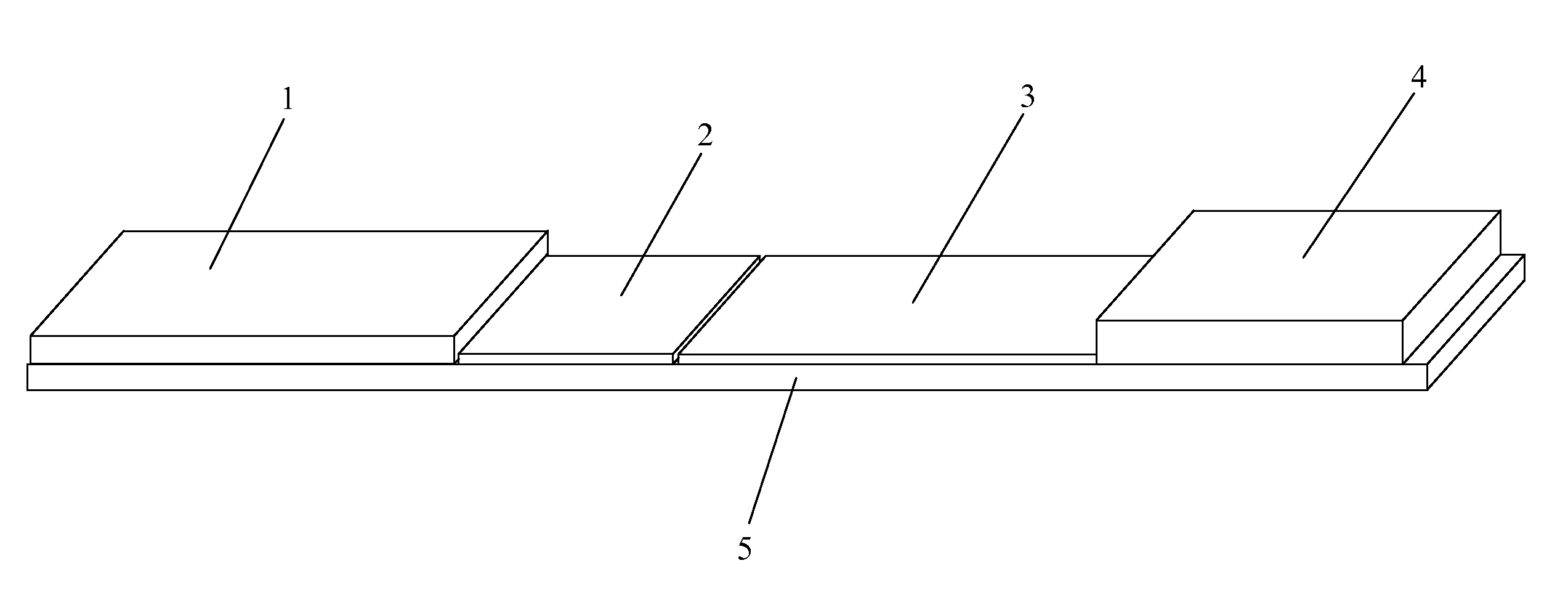
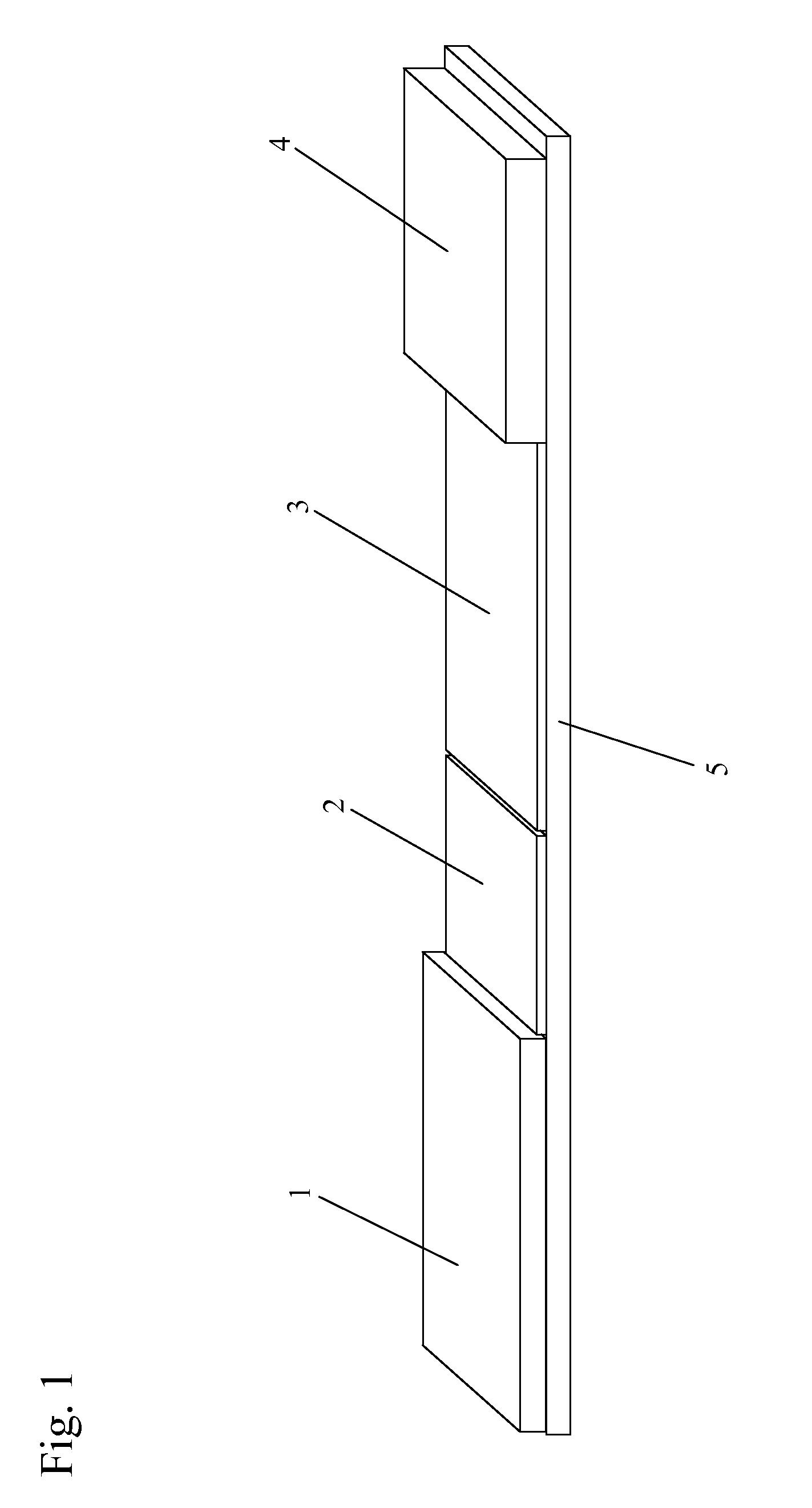
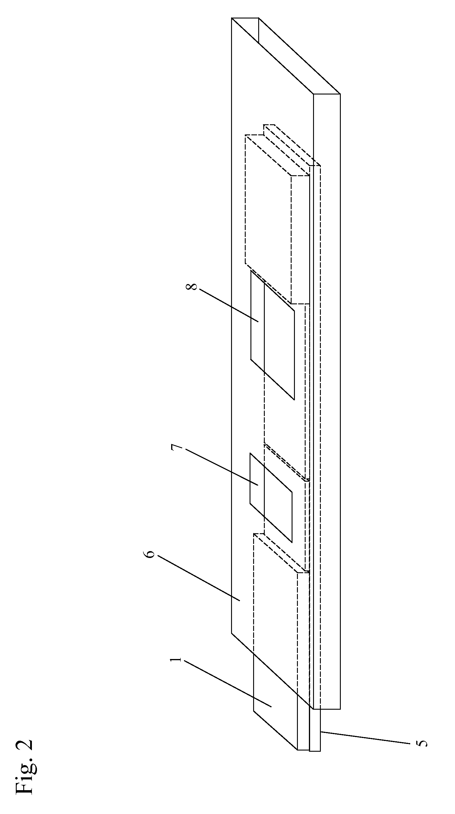
[0079]One or more lysis agents are dried onto the sample application zone of a lateral flow strip. On a per strip basis, the lysis agent is made of approximately 2 microliters of 100 mM HEPES buffer (pH 8.0) containing 5% CHAPS and 2% NP-40 with 150 mM Sodium Chloride, 0.1% BSA, and 0.1% Sodium Azide (all percentages weight / volume). Up to 10 microliters of whole blood are then added to the sample application zone to be lysed in situ. MxA protein is released from inside white blood cells to react with an MxA monoclonal antibody on a visual tag (colloidal gold or visible latex beads). This complex traverses with a running buffer containing Triton X-100 and is captured by MxA monoclonal antibodies immobilized at the test line of the nitrocellulose membrane. This binding at the test line gives rise to a visible indication.


PUM

PropertyMeasurementUnit
timeaaaaaaaaaa
pHaaaaaaaaaa
porosityaaaaaaaaaa

Abstract

Devices and methods incorporate lysis agents into a point-of-care testing device. The sample is loaded, and then the sample travels until it encounters a lysis agent. The lysis agent is preferably pre-loaded onto the collection device. In a preferred embodiment, the initially lysis agent is localized between the sample application zone and the conjugate zone. The lysis agent is preferably soluble or miscible in the sample transport liquid, and the lysis agent is solubilized and activated upon contact with the sample transport liquid. The sample transport liquid then contains both lysis agent in solution or suspension and sample components in suspension. Any lysis-susceptible components in a sample, then being exposed in suspension to the lysis agent, are themselves lysed in situ. The running buffer then carries the analyte, including any lysis-freed components, to the detection zone.

Description

REFERENCE TO RELATED APPLICATIONS[0001]This application claims one or more inventions which were disclosed in Provisional Application No. 61 / 080,879, filed Jul. 15, 2008, entitled “LATERAL FLOW NUCLEIC ACID DETECTOR”, Provisional Application No. 61 / 098,935, filed Sep. 22, 2008, entitled “IN SITU LYSIS OF CELLS IN LATERAL FLOW IMMUNOASSAYS”, and Provisional Application No. 61 / 179,059, filed May 18, 2009, entitled “METHOD AND DEVICE FOR COMBINED DETECTION OF VIRAL AND BACTERIAL INFECTIONS”. The benefit under 35 USC §119(e) of the U.S. provisional applications are hereby claimed, and the aforementioned applications are hereby incorporated herein by reference.[0002]This application is also a continuation-in-part application of application Ser. No. 12 / 469,207, filed May 20, 2009, entitled “NANOPARTICLES IN DIAGNOSTIC TESTS”, now abandoned, which claimed priority from Provisional Application No. 61 / 071,833, filed May 20, 2008, entitled “NANOPARTICLES IN DIAGNOSTIC TESTS” and application S...

Claims


Application Information

Patent Timeline
Patent Type & Authority Patents(United States)
IPC IPC(8): G01N33/558
CPCG01N33/558B01L3/5023B01L2300/0825Y10T436/25375G01N33/54388
Inventor VANDINE, ROBERT W.BABU, UMA MAHESHSAMBURSKY, ROBERT P.
Owner RAPID PATHOGEN SCREENING INC
Why Eureka
Try Eureka