Low-pressure valve with an inner and outer throughflow cross section

a technology of cross-sectional throughflow and low-pressure valve, which is applied in the direction of valve operating means/release devices, machines/engines, liquid fuel engines, etc., can solve the problems of large volumetric flow, low rotational speed, and low switching time requirements, and achieve the effect of improving functionality

Inactive Publication Date: 2013-12-31
ROBERT BOSCH GMBH
View PDF7 Cites 7 Cited by
  • Summary
  • Abstract
  • Description
  • Claims
  • Application Information

AI Technical Summary

Benefits of technology

[0008]By contrast, the disclosure is based on the object of providing a low-pressure valve of this generic type, the valve having improved functionality. Furthermore, a hydraulic machine equipped therewith is to be provided.
[0010]According to the disclosure, the electromagnetically actuated valve of the low-pressure-valve type is formed with a valve body which is assigned to a valve seat, is prestressed in a first direction, preferably the opening direction, and can be adjusted by means of a magnetic actuator in a second direction, preferably the closing direction. The valve is provided with a flat, preferably two-edge sealing system. This means that a flat or planar (plane) annular contact surface is formed on the valve body and can be brought into sealing contact with the likewise planar (plane) valve seat. The planar contact surfaces can be produced in a simple manner, ensure a fluidtight contact connection between the valve body and valve seat, and reduce the surface pressure.
[0011]It is advantageous to divide the contact surface of the valve body radially into an outer and inner sealing edge by an encircling (annular) groove. Said groove (weakening in the material) brings about easier axial movability of the inner sealing edge (sealing surface) with respect to the outer sealing edge (sealing surface) such that the two sealing edges can easily move relative to each other in the axial direction. The tightness of the valve can thereby be improved.
[0012]A preferred development of the disclosure makes provision for a relative tilting movement to be possible between a valve tappet or magnet armature and the valve body mounted thereon. This is structurally achieved by a bore in the valve body having a radial excess size in relation to the valve tappet or magnet armature such that the valve body is held on / at the valve tappet with radial play. The valve body or the planar contact surfaces thereof can thereby be placed in a sealing manner on the (planar) valve seat even if the valve seat is aligned with respect to the valve tappet with relatively great tolerances. The outlay on production can be further reduced as a result.
[0013]According to a particular aspect of the disclosure, the valve tappet is formed or provided with only one magnet armature, wherein the valve seat bushing itself has a guide bore for the axially displaceable mounting of the valve tappet. Said guide bore forms the sole mounting of the valve tappet, and therefore tolerance chains caused by components which are used for the mounting of the valve tappet and are constructed next to one another are not produced. By this means, the functional capability of the valve is improved and the outlay on manufacturing reduced.
[0014]According to a further particular aspect of the disclosure, the low-pressure or outlet valve equipped with a flat, preferably two-edge sealing system is formed merely with the valve seat bushing and without an outer valve housing, wherein the valve seat bushing is screwed directly into the housing of the hydraulic machine. That is to say, in this case, all of the fluid flow passages which are assigned to the low-pressure valve and to date were formed in the valve housing or the outer valve bushing are now formed in the housing of the hydraulic machine. It is thereby possible to increase the flow cross sections in the valve because of the omission of the outer valve bushing and therefore to realize an increased volumetric flow. In this case, the valve may have the multiple magnet-armature construction or the simplified individual magnet-armature construction.

Problems solved by technology

However, such a large flow cross section requires a greater valve lift, this contradicting the requirement for high valve dynamics with as little electrical power consumption as possible.
For example, large volumetric flows and requirements for low switching times arise from high rotational speeds, and low rotational speeds are associated with long switching-on periods for the magnet coils.
Although said undesirable closing movement could be countered by a more powerful opening spring, the valve dynamics would deteriorate as a result or a more powerful magnetic coil together with associated power electronics would be necessary.
In addition, this solution does not exhibit the desired dynamics either, since the field of the permanent magnet has to be weakened first before the valve element can be moved in the direction of the closed position thereof.

Method used


Image

  • Low-pressure valve with an inner and outer throughflow cross section
  • Low-pressure valve with an inner and outer throughflow cross section
  • Low-pressure valve with an inner and outer throughflow cross section

Examples


Embodiment Construction

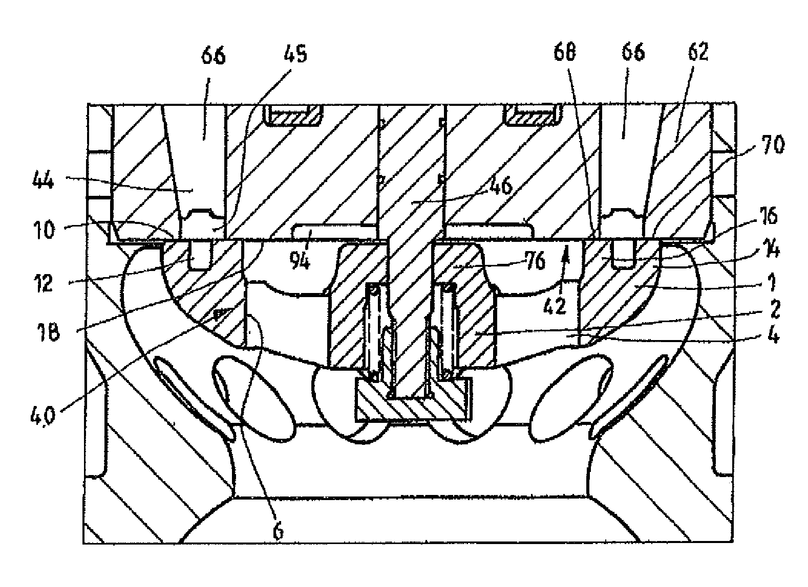
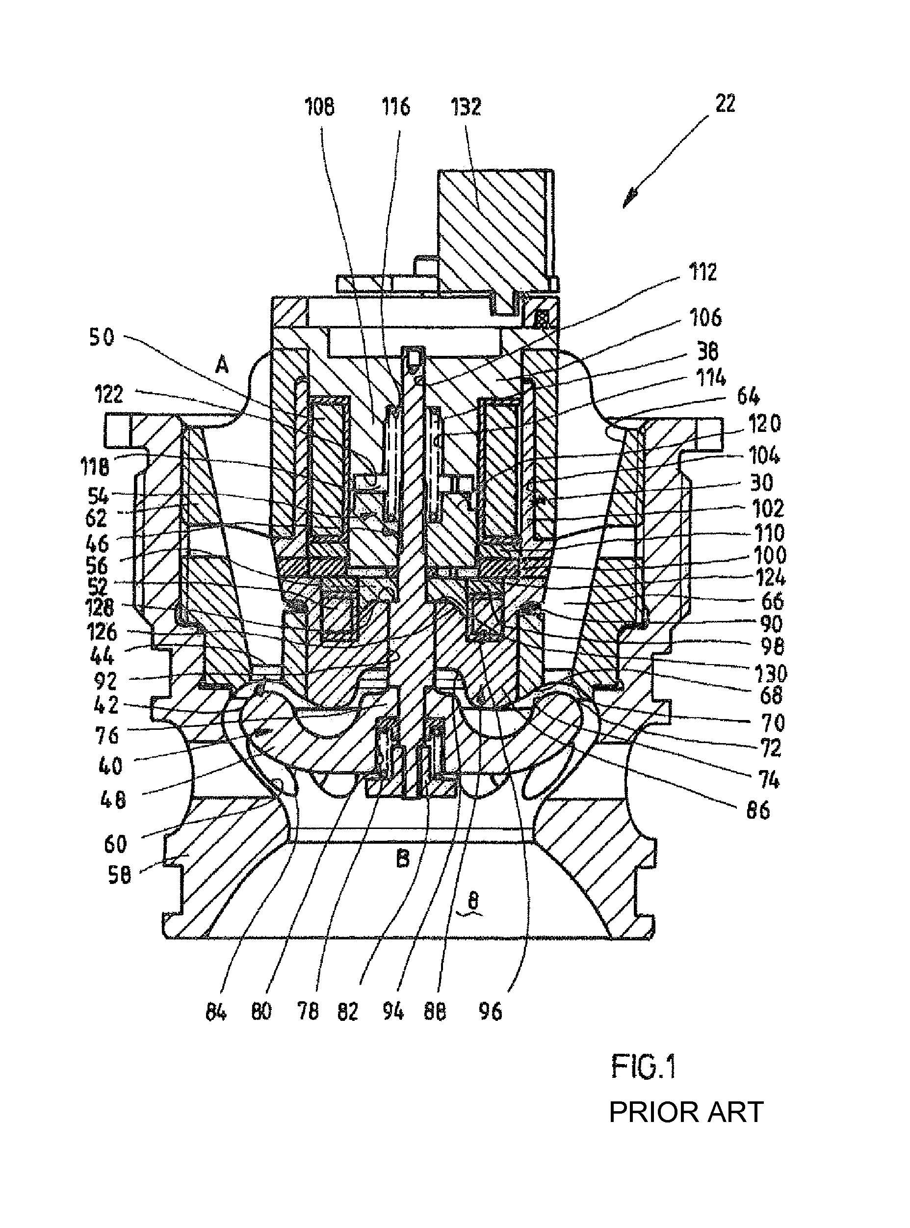
[0023]FIG. 1 shows the basic construction of a nonreturn valve on the low-pressure side, in the form of a reference valve for the subject matter of the disclosure, said valve corresponding to the outlet valve in a hydraulic motor. In a pump, the valve would be the inlet valve or suction valve.

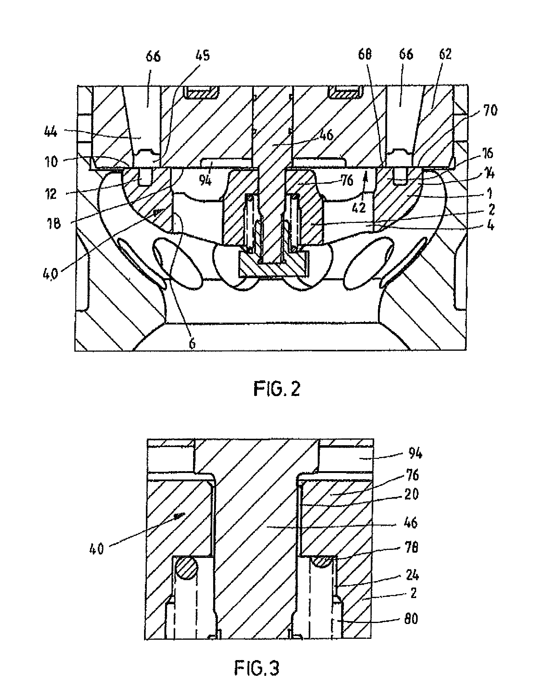
[0024]According to FIG. 1, the low-pressure valve or outlet valve 22 has a valve body 40 which is prestressed into an open position by a spring 38 and can be adjusted by means of a magnetic actuator 30 into a closed position against a valve seat 42 such that an annular throughflow cross section 44 is blocked. The outlet valve 22 is embodied in the form of a “disk valve”, the valve element 40 having a tappet 46 which bears an approximately mushroom-shaped closing disk 48 on the lower end section thereof in FIG. 1. When the throughflow cross section 44 is open (view according to FIG. 1), a pressure medium connection between a connecting passage A on the inlet side and a passage B opening in a wor...


PUM


Abstract

An electromagnetically actuated valve with a valve body which is assigned to a valve seat, is mechanically prestressed in a first direction toward a first switching position and can be adjusted by means of a magnetic actuator in a second, opposite direction into a second switching position is disclosed. The valve body has a planar contact surface which can be brought into sealing contact with a surface of the valve seat, which surface is planar at least in sections.

Description

[0001]This application claims priority under 35 U.S.C. §119 to German patent application no. 10 2010 005 168.3, filed Jan. 20, 2010, the disclosure of which is incorporated herein by reference in its entirety.BACKGROUND[0002]The disclosure relates to a preferably electro-magnetically actuated valve and in particular to a low-pressure valve, as used, for example, in a hydraulic machine.[0003]Valve-controlled hydraulic machines of this type are known, for example, from EP 1 537 333 B1. The European patent document shows a hydraulic machine of axial or radial piston construction which can be operated in principle as a motor or as a pump, with the volumetric delivery or capacity being adjustable via the valve timing gear. In an exemplary embodiment which is described, the hydraulic machine is embodied in the form of an axial piston machine, wherein a multiplicity of pistons arranged in a cylinder is supported on a rotatably mounted swash plate. Each piston together with the associated c...

Claims


Application Information

Patent Timeline
Patent Type & Authority Patents(United States)
IPC IPC(8): F16K31/02
CPCF16K31/0655F04B53/1082F16K1/12Y10T137/786Y10T137/7861F16K1/36F16K1/44
Inventor DUERR, MICHAELWEINGART, JOERGSCHWADERER, PETER
Owner ROBERT BOSCH GMBH
Why Eureka
Try Eureka