Power amplifier and power amplifying method

a power amplifier and amplifier technology, applied in the direction of amplifier modification to reduce non-linear distortion, digital transmission, baseband system details, etc., can solve the problems of power amplifier power efficiency reduction, power amplifier power efficiency improvement, power amplifier power consumption, etc., to improve signal accuracy and reduce power consumption. the effect of power amplifier

Active Publication Date: 2013-12-31
NEC CORP
View PDF12 Cites 9 Cited by
  • Summary
  • Abstract
  • Description
  • Claims
  • Application Information

AI Technical Summary

Benefits of technology

[0020]According to a power amplifier and a power amplifying method according to the present invention, it is possible to reduce power consumption in the power amplifier while improving the signal accuracy.

Problems solved by technology

A transmission power amplifier (Power Amplifier: PA) used in a radio communication device especially consumes high power in the communication device.
Accordingly, improving power efficiency of the power amplifier is the most important issue in developing communication devices.
However, performance of the deep back-of operation leads to reduction in power efficiency in the power amplification.
However, according to this system, the signal distortion in the desired signal band (i.e. low frequency) cannot be corrected.
Further, since the output impedance of the current source is high, the unnecessary power due to the short-circuit between the voltage source and the current source does not flow.

Method used


Image

  • Power amplifier and power amplifying method
  • Power amplifier and power amplifying method
  • Power amplifier and power amplifying method

Examples


first exemplary embodiment

Variant Example of First Exemplary Embodiment

[0076]A power supply modulator 20b according to a variant example of the first exemplary embodiment shown in FIG. 13 will be described. The power supply modulator 20b is used in place of the power supply modulator 20. The power supply modulator 20b includes a current source 24a used in place of the current source 24 of the power supply modulator 20. The current source 24a includes a pulse signal source 38 in place of the pulse modulator 34. The pulse modulator 38 has a function of calculating and outputting a pulse signal VG which is the same to the pulse signal output from the pulse modulator 34 of the power supply modulator 20 in advance. Further, the pulse signal source 38 has a function of setting the output timings of the low-frequency amplitude modulated signal VC_L, the high-frequency amplitude modulated signal VC_H, and the pulse signal VG to a desired value by being synchronized with the low-frequency signal source 31 and the hig...

second exemplary embodiment

Variant Example of Second Exemplary Embodiment

[0081]A power supply modulator 40a according to a variant example of the second exemplary embodiment shown in FIG. 15 will be described. The power supply modulator 40a is used in place of the power supply modulator 40. The power supply modulator 40a includes a current source 27a used in place of the current source 27 of the power supply modulator 40. The current source 27a includes a pulse signal source 38 in place of the pulse modulator 34. In the power supply modulator 40a, the resistor Rs may be removed or short-circuited, or may be implemented.

[0082]Also in the variant example of the second exemplary embodiment, as is similar to the variant example of the first exemplary embodiment, the output timings of the low-frequency amplitude modulated signal VC_L, the high-frequency amplitude modulated signal VC_H, and the pulse signal VG are adjusted, thereby being capable of correcting the error caused by the delay of the current IM and the ...

third exemplary embodiment

Variant Example of Third Exemplary Embodiment

[0106]A power supply modulator 50a according to a variant example of the third exemplary embodiment shown in FIG. 19 will be described. The power supply modulator 50a is used in place of the power supply modulator 50. The power supply modulator 50a includes a current source 28a in place of the current source 28 used in the power supply modulator 50. The current source 28a includes a pulse signal source 38 in place of the pulse modulator 34. The register Rs may be removed and short-circuited in the power supply modulator 50a, or may be implemented.

[0107]Also in the variant example according to the third exemplary embodiment, the output timings of the low-frequency amplitude modulated signal VC_L, the high-frequency amplitude modulated signal VC_H, and the pulse signal VG are adjusted as is similar to the variant example of the first exemplary embodiment, whereby the error caused due to the delay of the current IM and the amplitude modulate...


PUM


Abstract

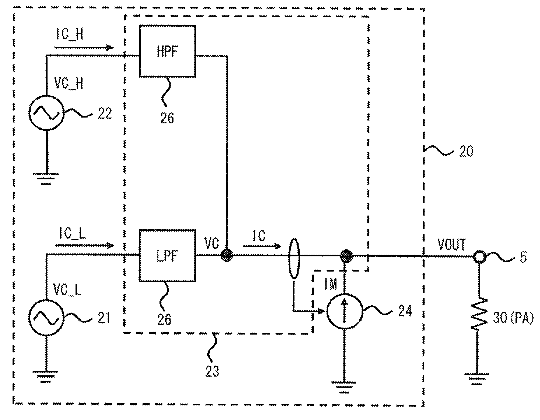
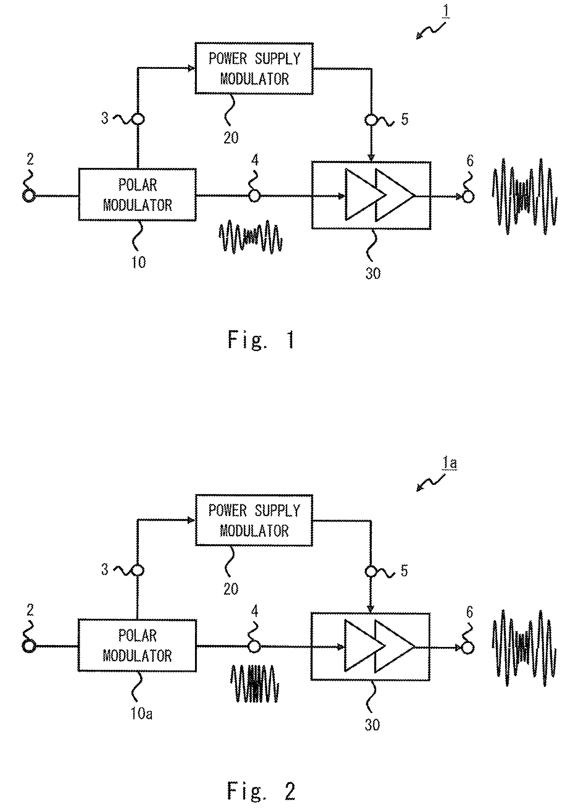
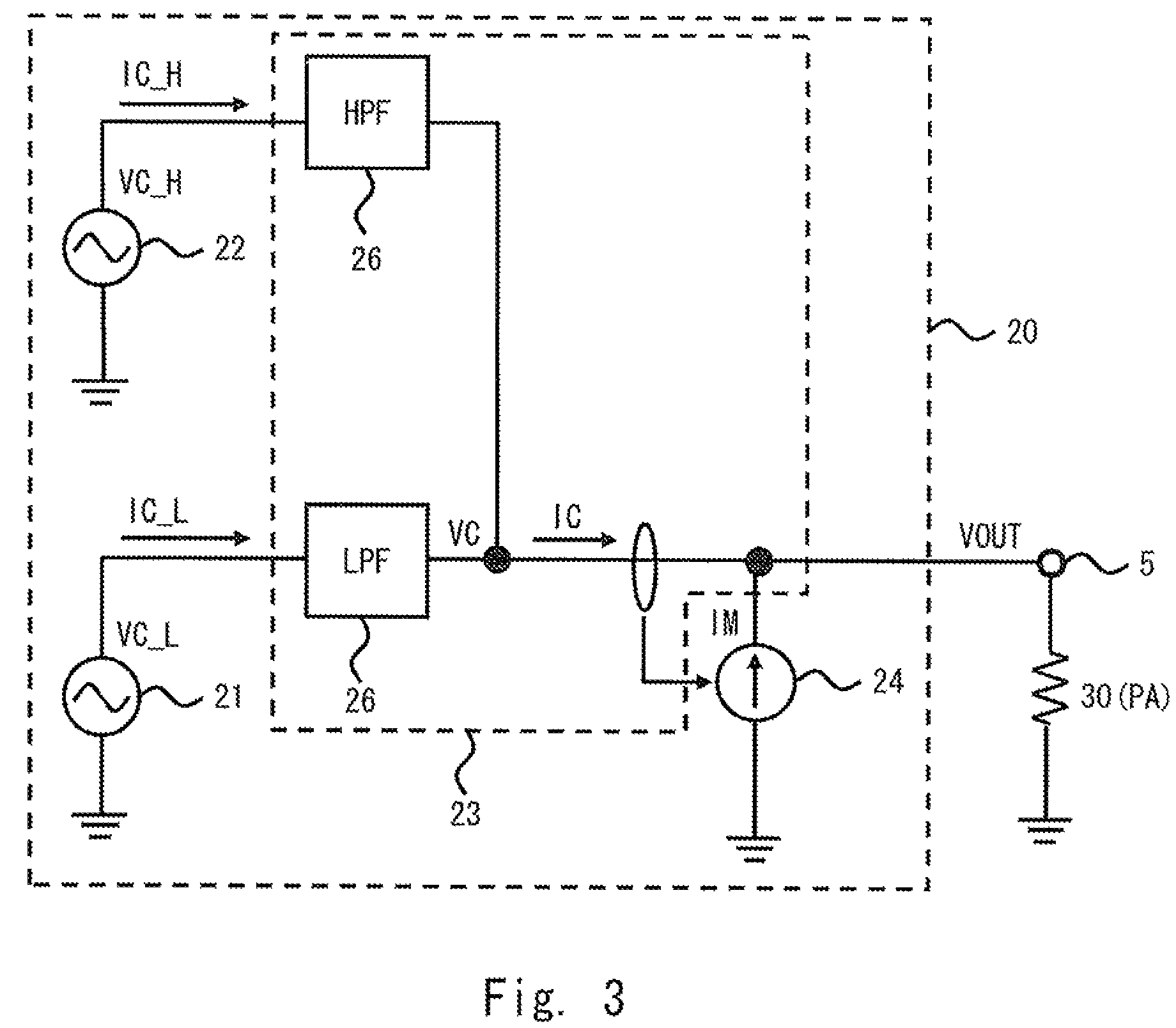
An aspect of a power amplifier according to the present invention is a power amplifier that amplifies a modulated signal including amplitude modulated components and phase modulated components, the power amplifier including a first voltage source 21 that amplifies low-frequency components of the amplitude modulated components of the modulated signal to output a first voltage VC_L, a second voltage source 22 that amplifies high-frequency components of the amplitude modulated components of the modulated signal to output a second voltage VC_H, a current source 24 that amplifies amplitude components of the modulated signal to output a current, a combiner circuit 23 that combines the first voltage VC_L, the second voltage VC_H, and a current IM to generate a modulated power supply signal VOUT, and an RF amplifier 30 that amplifies a signal obtained by up-converting the modulated signal to a carrier frequency and outputs the amplified signal after modulating amplitude of the amplified signal by the modulated power supply signal VOUT. In this way, power efficiency of a circuit that generates a modulated power supply can be improved.

Description

TECHNICAL FIELD[0001]The present invention relates to a power amplifier and a power amplifying method, and more specifically, to a power amplifier and a power amplifying method that amplify a modulated signal including amplitude modulated components and phase modulated components.BACKGROUND ART[0002]A transmission power amplifier (Power Amplifier: PA) used in a radio communication device especially consumes high power in the communication device. Accordingly, improving power efficiency of the power amplifier is the most important issue in developing communication devices. According to a recent communication standard, performing amplitude modulation has become the mainstream in order to achieve spectral efficiency. This amplitude modulation strictly requires avoidance of signal distortion. Therefore, the power amplifier used in the communication device is operated with deep back-off (i.e. low input power) state in order to improve linearity. However, performance of the deep back-of o...

Claims


Application Information

Patent Timeline
Patent Type & Authority Patents(United States)
IPC IPC(8): H04B1/04H01Q11/12
CPCH03F2203/21142H03F3/245H03F1/0227H03F2200/411H03F3/211H03F2200/451H03F2200/204H03F3/189H03F2200/432H03F1/32
Inventor YAMANOUCHI, SHINGOKUNIHIRO, KAZUAKISHIIKUMA, KAZUMI
Owner NEC CORP
Why Eureka
Try Eureka