
Electrodynamic linear oscillating motor

a linear oscillating motor and electrodynamic technology, applied in the direction of motor/generator/converter stopper, dynamo-electric converter control, piston pump, etc., can solve the problems of low efficiency of less than 50% to 70%, high proportion of drive energy lost in springs, and design-related disadvantages of both mm motors and mc motors, etc., to achieve high drive power, low weight, and high power density

Inactive Publication Date: 2014-01-07
INST FUER LUFT & KAELTETECHNIK GEMEINNUETZIGE GMBH
View PDF33 Cites 28 Cited by
  • Summary
  • Abstract
  • Description
  • Claims
  • Application Information

AI Technical Summary

Benefits of technology

The invention is a special motor that can move back and forth very quickly. It is very powerful and can be controlled very easily. This motor can be used to control things like fuel injection in engines, and it is much lighter than traditional motors. It also uses less energy and is more efficient. This makes it a great choice for use in automobiles.

Problems solved by technology

The drawback is that such systems achieve a low efficiency of less than 50% to 70%, because approx.
Inherent to the use of Maxwell linear motors to drive reciprocating compressors, is that a high proportion of the drive energy is lost in the springs.
Nevertheless, both MM motors and MC motors suffer certain design-related disadvantages.
A disadvantage, however, is that there is no magnetic position reset.
MM linear motors have the disadvantage, however, that the magnetic flux density in the magnet gap of the motor is relatively low, because the permanent magnet in the movable system must be constructed as small and light as possible, in order not to impair the kinetics of the oscillating system.
The resulting reduced drive forces can possibly be compensated with higher speeds of the oscillating system, but high speeds of the oscillating system are undesired in some uses, for example, as the drive of a reciprocating compressor.
The system design is furthermore relatively complicated; it requires, in particular, two cost-intensive, radially magnetized permanent magnets.
Furthermore, the design of the magnet circuit is disadvantageous in that it does not permit flux concentration in the magnet gap, which makes it impossible for such motors to achieve high force and power densities.

Method used


Image

  • Electrodynamic linear oscillating motor
  • Electrodynamic linear oscillating motor

Examples


Embodiment Construction

[0031]The present invention will now be described more fully in detail with reference to the accompanying drawings, in which the preferred embodiments of the invention are shown. This invention should not, however, be construed as limited to the embodiments set forth herein; rather, they are provided so that this disclosure will be complete and will fully convey the scope of the invention to those skilled in the art.

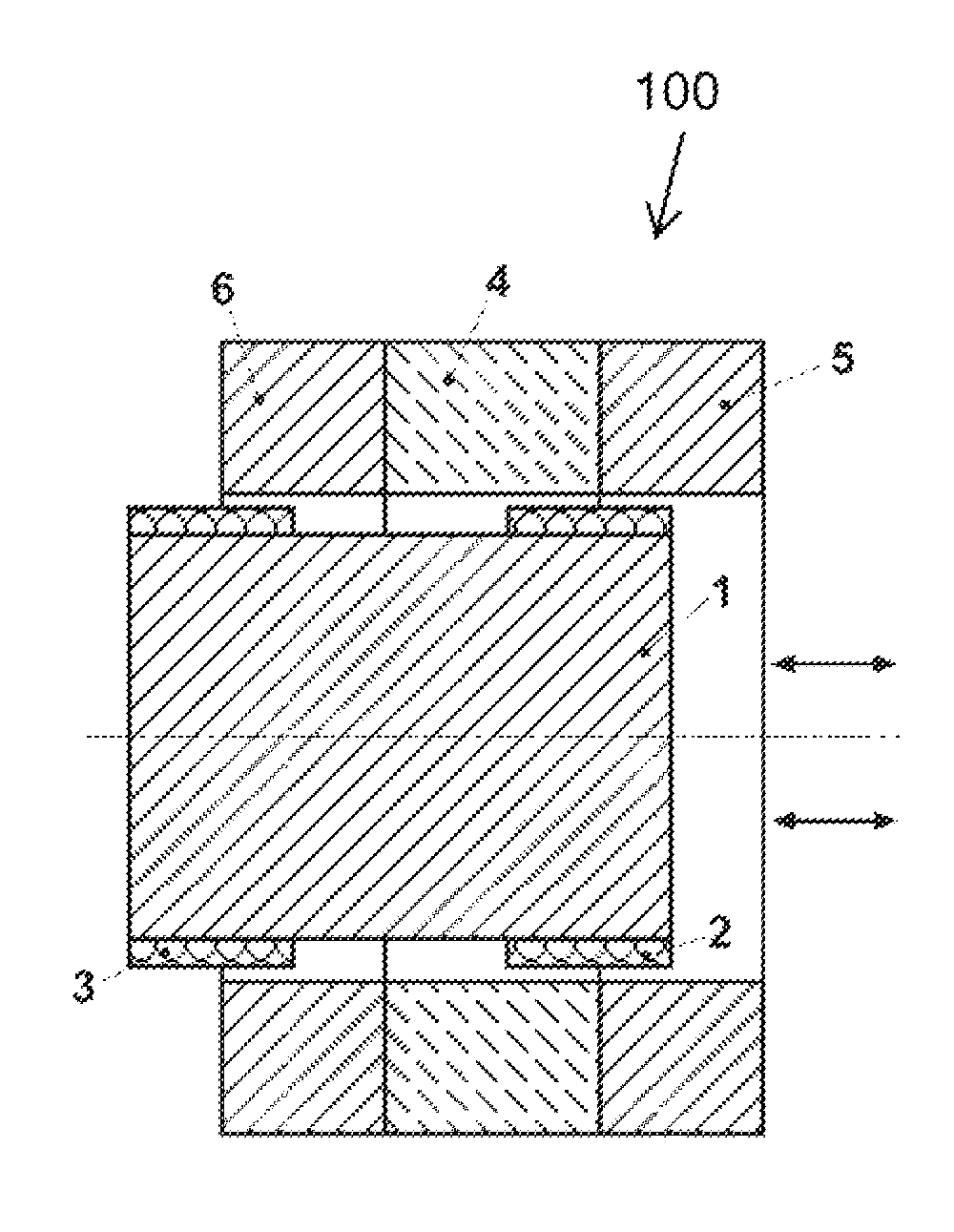
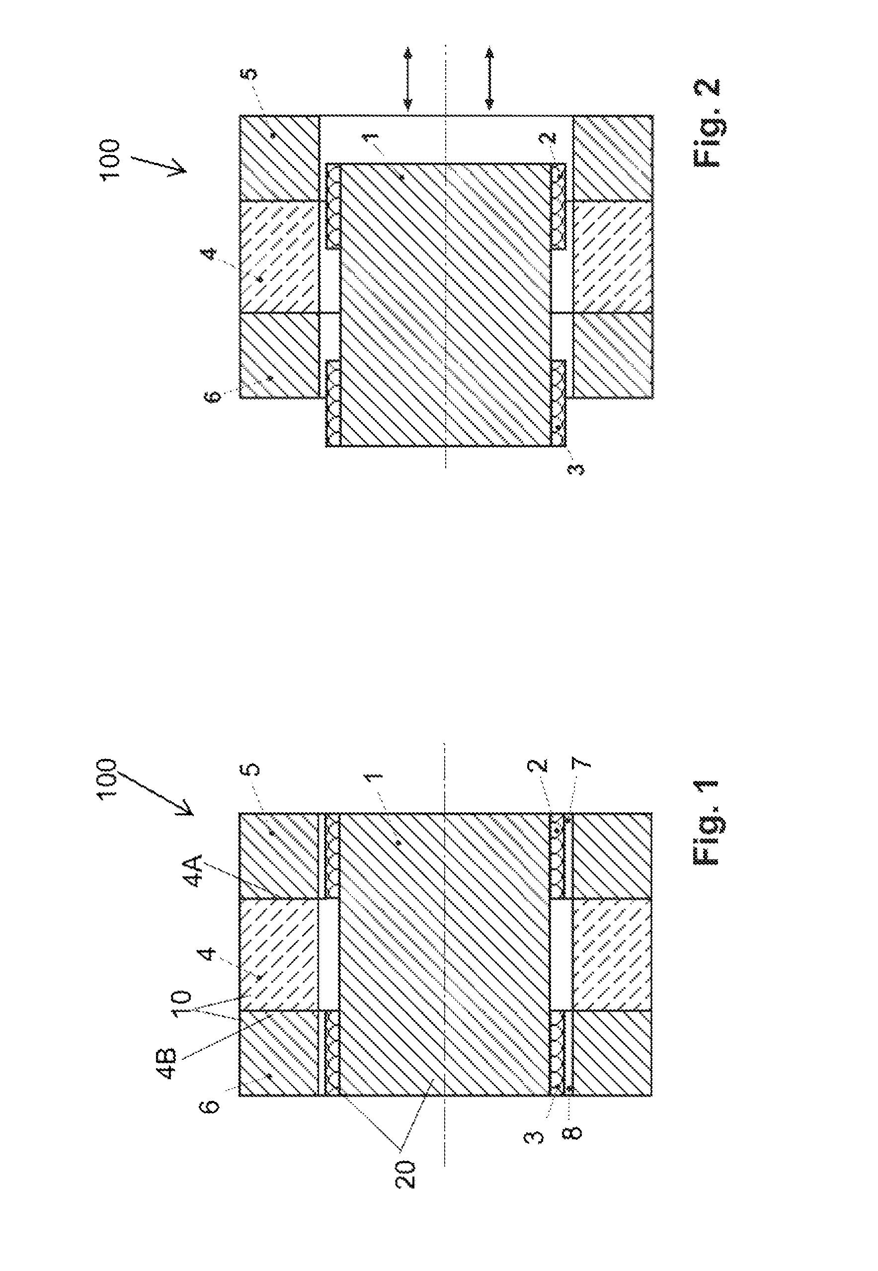
[0032]FIGS. 1 and 2 are schematic illustrations in cross-section of a linear oscillating motor 100 according to the invention, in an embodiment constructed for a typical small refrigeration compressor. This particular embodiment of the linear oscillating motor is for illustration purposes and is not intended to be limiting to the scope of the invention.

[0033]The linear oscillating motor 100 comprises a stator system 10 and an oscillating system 20. The stator system 10 comprises an annular annular-disk-shaped permanent magnet or electromagnet 4, a first ring-shaped pole ...


PUM


Abstract

The invention is an electrodynamic linear oscillating motor, which has high power densities in the magnet gap, a high efficiency, and magnetically restores the oscillating system to a center position. The linear oscillating motor has a stator system, which has at least one magnet, and an oscillating system, which is movably mounted in the magnetic field of the stator. The oscillating system has at least one core made of a soft magnetic material, and at least one driving coil. The electrodynamic linear motor combines the advantages of the known moving coil and moving magnet linear motor, achieving electrodynamic conversion levels of up to 99%. The motor is suited as a drive for refrigerating and air conditioning systems having low power and also for pumping and injection systems, and, reversing the electrodynamic principle, as a generator, such as for shock absorber systems in a motor vehicle.

Description

BACKGROUND INFORMATION[0001]1. Field of the Invention[0002]The invention relates to an electrodynamic linear oscillating motor. More particularly, the invention relates to a linear oscillating motor that is particularly well suited for use as a drive in refrigeration and air-conditioning equipment requiring low output and for pump, injection, and shock-absorption systems in motor vehicles.[0003]2. Discussion of the Prior Art[0004]The compressors of low-power refrigeration and air-conditioning systems, as used in particular in household applications, are usually reciprocating compressors. For economic reasons, rotary compressors, for example, scroll compressors, are only used for equipment having a drive output of several kilowatts.[0005]Reciprocating compressors are usually driven by electric motors which produce a rotary motion and, consequently, crank mechanisms are required to convert this rotary motion into the translational or reciprocating motion required for operation of the ...

Claims


Application Information

Patent Timeline
IPC IPC(8): H02K33/18H02K35/04H02K33/00
CPCH02K35/04H02K33/18
Inventor KAISER, GUNTERKLIER, JUERGEN
Owner INST FUER LUFT & KAELTETECHNIK GEMEINNUETZIGE GMBH
Learn More