Filling fenestration units

a technology of fenestration units and aerogel particles, which is applied in the field of insulated systems, can solve the problems of uneven translucence, diminished insulating properties, and difficulty in filling the internal cavity of such units, and achieve excellent insulating and optical properties, reduce or minimize settling, and increase the demand for energy conservation

Active Publication Date: 2014-01-14
CABOT CORP
View PDF62 Cites 0 Cited by
  • Summary
  • Abstract
  • Description
  • Claims
  • Application Information

AI Technical Summary

Benefits of technology

[0012]The invention addresses the increased demand for energy conservation and “green” construction practices and materials and has many advantages. For example, window units manufactured using the method of the invention have excellent insulating and optical properties. Practicing the invention allows for the filling of cavities with aerogel and reduces or minimizes settling and can add to the overall mechanical stability of the system. In glass units, the invention can result in a finished product having essentially parallel panes and little optical distortion. The invention also can reduce or minimize the need for internal reinforcements in polycarbonate systems and is particularly well suited for fabricating relatively large, un-reinforced daylighting systems. In some aspects, practicing the invention reduces or minimizes crack formation and breakage. Filling fenestration units with blends of aerogel and non-aerogel materials presents cost advantages and added flexibility within a product line. In spandrel applications, fenestration units such as described herein and filled with an insulator containing aerogel and, optionally a non-aerogel material, can be glazed into the profiled system as a finished unit, eliminating the back pans, other insulating materials and labor required to fabricate and install them.

Problems solved by technology

Filling the internal cavity of such units with aerogel particles, however, continues to present challenges.
Inadequate techniques can lead to “settling”, resulting in diminished insulating properties and uneven translucence.

Method used


Image

  • Filling fenestration units
  • Filling fenestration units
  • Filling fenestration units

Examples


Embodiment Construction

[0024]The above and other features of the invention including various details of construction and combinations of parts, and other advantages, will now be more particularly described with reference to the accompanying drawings and pointed out in the claims. It will be understood that the particular method and device embodying the invention are shown by way of illustration and not as a limitation of the invention. The principles and features of this invention may be employed in various and numerous embodiments without departing from the scope of the invention.

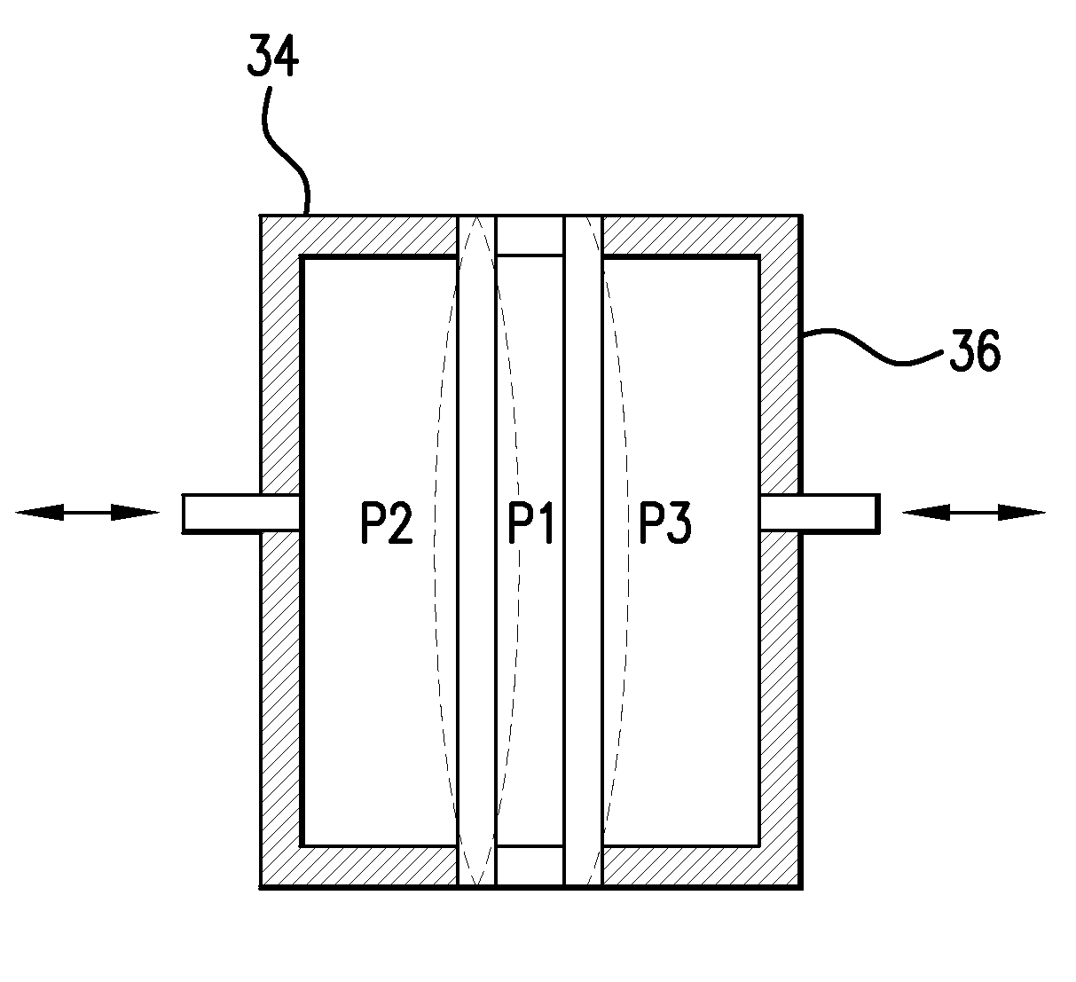
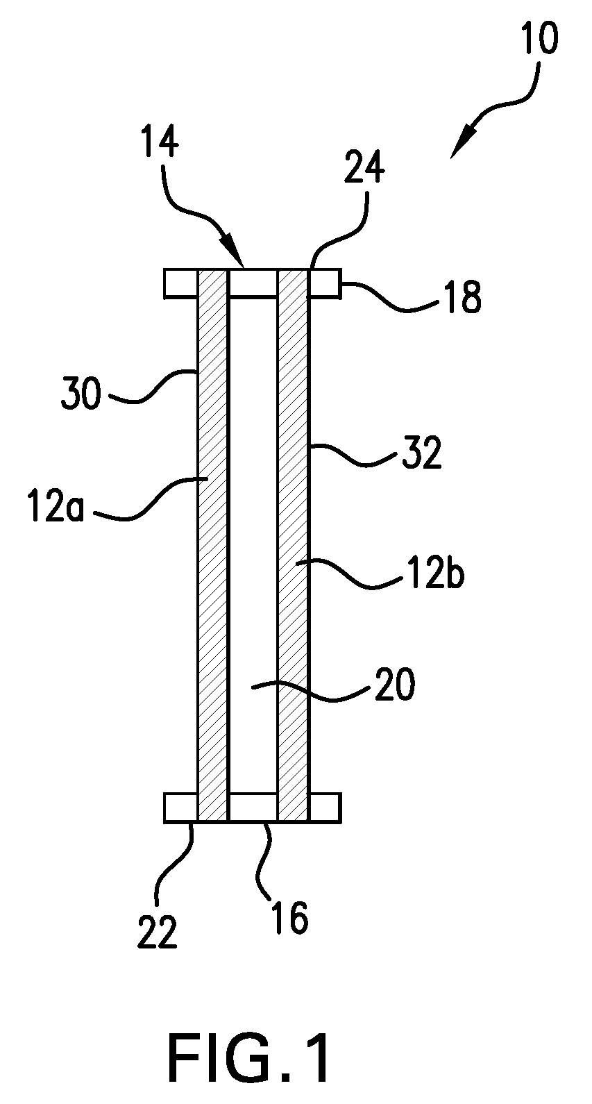
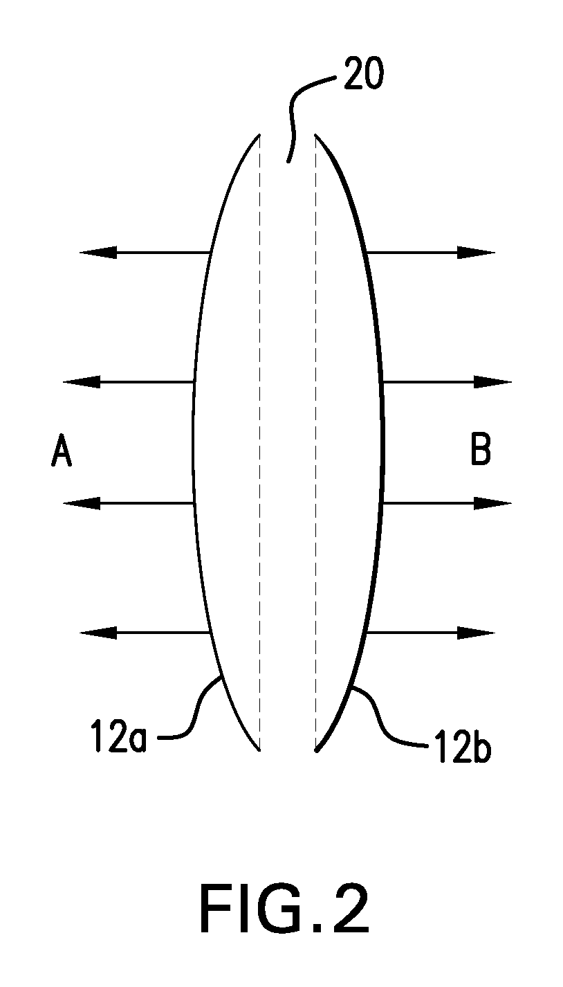
[0025]The invention generally relates to insulated systems such as fenestration units and methods for producing them. The insulated systems can be used in buildings and other types of construction, transportation, storage containers, refrigeration, green houses, manufacturing or processing units and so forth.

[0026]Many embodiments of the invention relate to an insulating system which includes two or more walls and an insulator, ...


PUM

PropertyMeasurementUnit
light transmittanceaaaaaaaaaa
surface areaaaaaaaaaaa
thicknessaaaaaaaaaa

Abstract

A method for fabricating an insulated system such as, for instance, an insulated window unit, includes introducing an insulating material between adjacent walls and stabilizing the system. Particulate insulators preferably are introduced in the system by filling an expanded internal volume. Stabilization of the system can be carried out by reducing the pressure within the internal volume. A stabilized insulated system is fabricated by introducing an insulating material between adjacent walls and stabilizing the system. Also disclosed are processes and equipment for filling insulated systems, such as fenestration units, and insulated systems comprising mixed insulating materials.

Description

RELATED APPLICATIONS[0001]This application claims the benefit of U.S. Provisional Patent Application No. 60 / 938,935, with the title Filling and Stabilization of Aerogel Insulated Systems, filed May 18, 2007 and of U.S. Provisional Patent Application No. 60 / 951,054 filed Jul. 20, 2007, with the title Filling Fenestration Units, the contents of both being incorporated herein by reference in their entirety.BACKGROUND OF THE INVENTION[0002]Insulated windows and spandrel panels are increasingly used in residential and commercial buildings. Double pane, as well as triple pane, and even quadruple pane window units are available. In many existing insulated windows the internal space is filled with air. Sometimes the internal space is filled with a gas such as argon or krypton for better thermal resistance value. Insulated glass units and daylighting systems that employ particulate aerogel material also are becoming available.[0003]Filling the internal cavity of such units with aerogel parti...

Claims


Application Information

Patent Timeline
Patent Type & Authority Patents(United States)
IPC IPC(8): B32B17/10B32B17/08
CPCE06B3/6775Y02B80/26Y10T428/231Y10T29/49893Y10T428/239Y10T428/234Y10T29/49892Y02A30/249Y02B80/22
Inventor DU PLESSIS, ANDRIES J.GERTNER, GEORG RUDOLFSATTERWHITE, JAMES R.OLSEN, DANIEL P.
Owner CABOT CORP
Why Eureka
Try Eureka