[0006]It is an object of certain aspects of the invention to facilitate connecting sheet metal parts by means of welding or soldering and to improve the outer appearance of such a composite of sheet metal parts. Preferably, the quality of the connection is also improved.
[0012]It is advantageous if the seam runs along the flange edge. However, the flange edge can serve only as a rough orientation for the seam. In such embodiments, although most preferred, the seam runs in a short distance from the flange edge, preferably parallel to the flange edge. In principal, however, the seam may run anywhere between the flange edge and the bent transition formed between the first outer shell region and the first joining region as long as it is hidden, i.e. as long as it does not reach to the bent transition of the first sheet metal part and also not to the bent transition of the second sheet metal part. The seam may be, for example, wound. As in the other embodiments, the seam runs at a distance from the outer shell regions so that it can not be seen from outside. To hide the seam even more secure, the joining regions preferably abut each other and form a very narrow gap between the seam and the outer shall regions. This is, however, advantageous also for all other embodiments.
[0013]A flange edge with a projecting flange is advantageous in order to predefine the seam accurately or to stiffen any of the sheet metal parts in its joining region.
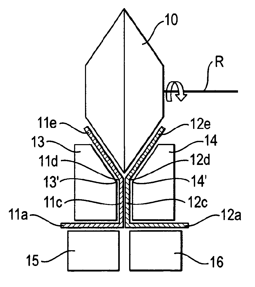
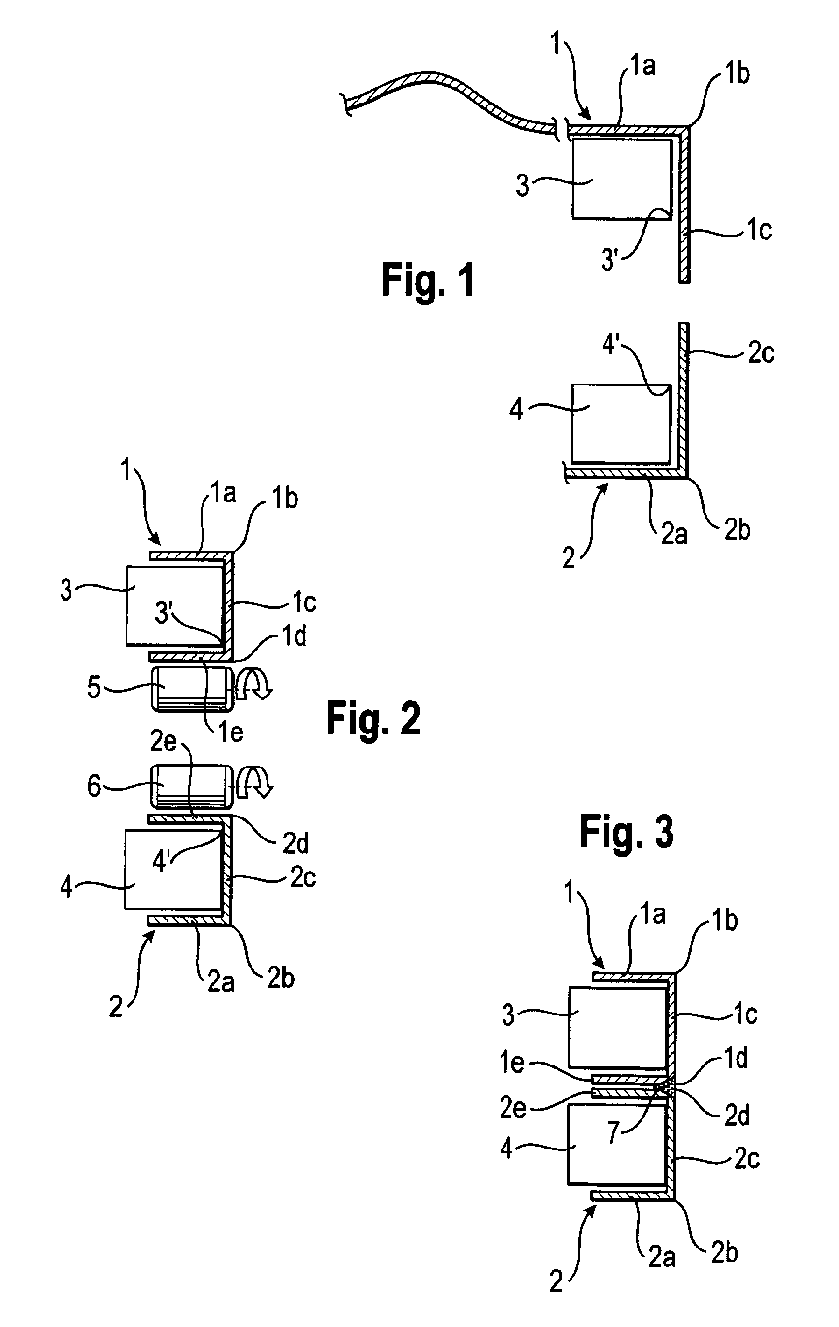
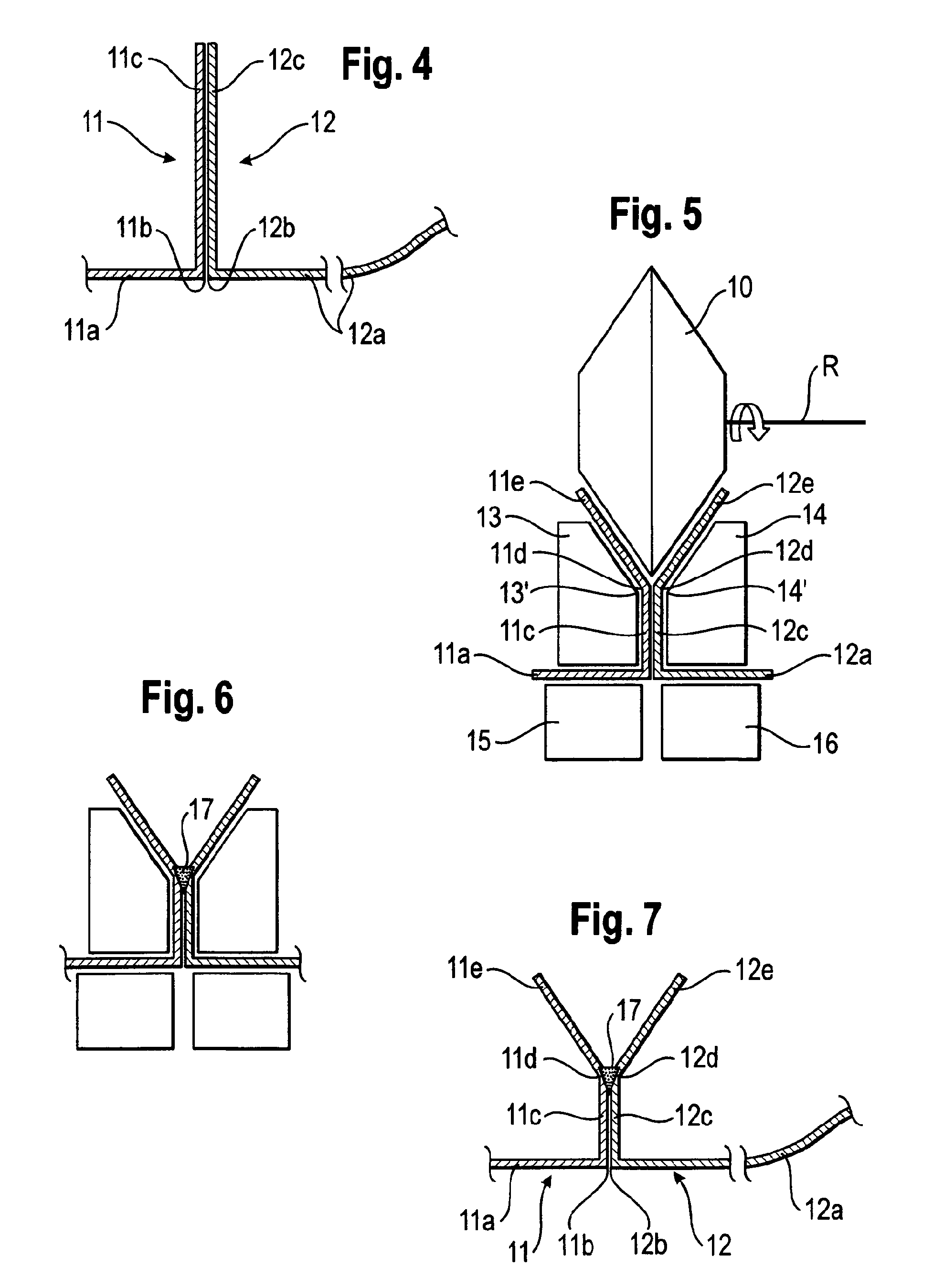
[0015]The first joining region can advantageously be a peripheral strip of the first sheet metal part deviating along the bent transition which preferably is a sharp edge with a small radius of curvature. The flange edge shaped in accordance with the preferred embodiment of the invention can be orientated in any way with respect to the bent transition, but can in particular run parallel to the transition. The flange is preferably folded in the same angular direction in which the joining region also projects from the adjacent first outer shell region. By flanging in accordance with the invention, the flange can be folded relative to the joining region by for example 30°, 45° or 90°, or as applicable also by a greater angle or by a value in between. In one variant, both the bent transition at which the joining region projects from the adjacent sheet metal region and the flange edge running within the joining region are shaped by flanging. If the second sheet metal part also comprises such a joining region, along which it is placed facing and preferably abuting the joining region of the first sheet metal part, and if the sheet metal parts are thus fixed relative to each other in the joining position, then in preferred embodiments, the flange of the first sheet metal part, which is angled away from the joining region, forms a funnel, as viewed in cross-section, together with the joining region of the second sheet metal part which is preferably also a peripheral strip. In order to further improve the welding or soldering result, the joining region of the second sheet metal part is advantageously also flanged in accordance with the invention, such that the sheet metal parts are fixed facing each other via the joining regions and the two flanged flanges point away from each other, preferably in a V-shape, wherein the joining regions preferably abut each other. The flange edges of the sheet metal parts oppose each other at a small distance or abut each other. An exactly defined, preferably narrow joint gap is obtained immediately at or above the flange edges along the entire flange, such that an accurate, uniform welding or soldering seam can be produced.
[0027]Forming the flange edge and the flange in an extra flanging step by means of a flanging element which moves in the longitudinal direction of the flange edge or transversely thereto is advantageous for producing composites of sheet metal parts by welding or soldering in general and not only for creating and joining the sheet metal parts to a composite with the claimed geometry or the claimed orientation with respect to outside and inside. However, such a flanging and subsequent welding or soldering is particularly well suited for producing the composite of the present invention.
[0028]Under the aspect of forming the flange edge(s) and flange(s) in an extra flanging step, the subject of the invention also includes a composite of sheet metal parts as such, which consists of at least two sheet metal parts, namely a first sheet metal part comprising a flange edge shaped by flanging and along which a flange projects, and a second sheet metal part which is connected to the first sheet metal part by means of a welding or soldering seam extending along the flange edge. The second sheet metal part preferably also comprises a flange edge shaped by flanging, and the seam also extends along this flange edge, i.e. from flange edge to flange edge as viewed in cross-section. The flange edge of the second sheet metal part can likewise be shaped by flanging, preferably as disclosed with respect to the first sheet metal part. The composite of sheet metal parts can in particular be manufactured using the method in accordance with the flanging alternative of claim 7. The fact that the flange or number of flanges has been folded by flanging can for example be seen from the surface of the respective flange on which the longitudinally advancing flanging element leaves behind the streaks which are typical of flanging if the flange has not been worked after flanging. With flanging, the metal sheet is more uniformly loaded than for example when folded in a folding press or when embossed or deep-drawn in a press, such that the material microstructure of low crack density of the metal sheet continues more uniformly into the flanged edge than in the other deforming processes cited by way of example. In many cases, this can even be seen with the naked eye, or at least under the microscope. Furthermore, the flanged flange edge is particularly well-defined, i.e. it exhibits the same course from sheet metal part to sheet metal part and also the same cross-sectional shape at the same location along its course. The quality of the seam and of the connection as a whole can be further increased if the sheet metal parts are flanged in the joining position, preferably in the same run of the flanging tool and even more advantageously using the same flanging element. The welding or soldering tool is placed and moved along the flange edge, producing the connecting seam, preferably by adding welding or soldering material, while the fixation of the flanging process is maintained. Flanging can be followed by welding or soldering, without any intermediate step.

