
Method of manufacturing a semiconductor device

a technology of metal gate and semiconductor, applied in the direction of semiconductor devices, basic electric elements, electrical equipment, etc., can solve the problems of excessively high gate resistance caused by polysilicon gate electrodes, increase in leakage current and power consumption, and increase in the thickness of the interface layer, so as to prevent the increase in the thickness of the sio2 interface layer and effectively reduce the eot of the device

Active Publication Date: 2014-01-21
INST OF MICROELECTRONICS CHINESE ACAD OF SCI
View PDF2 Cites 1 Cited by
  • Summary
  • Abstract
  • Description
  • Claims
  • Application Information

AI Technical Summary

Benefits of technology

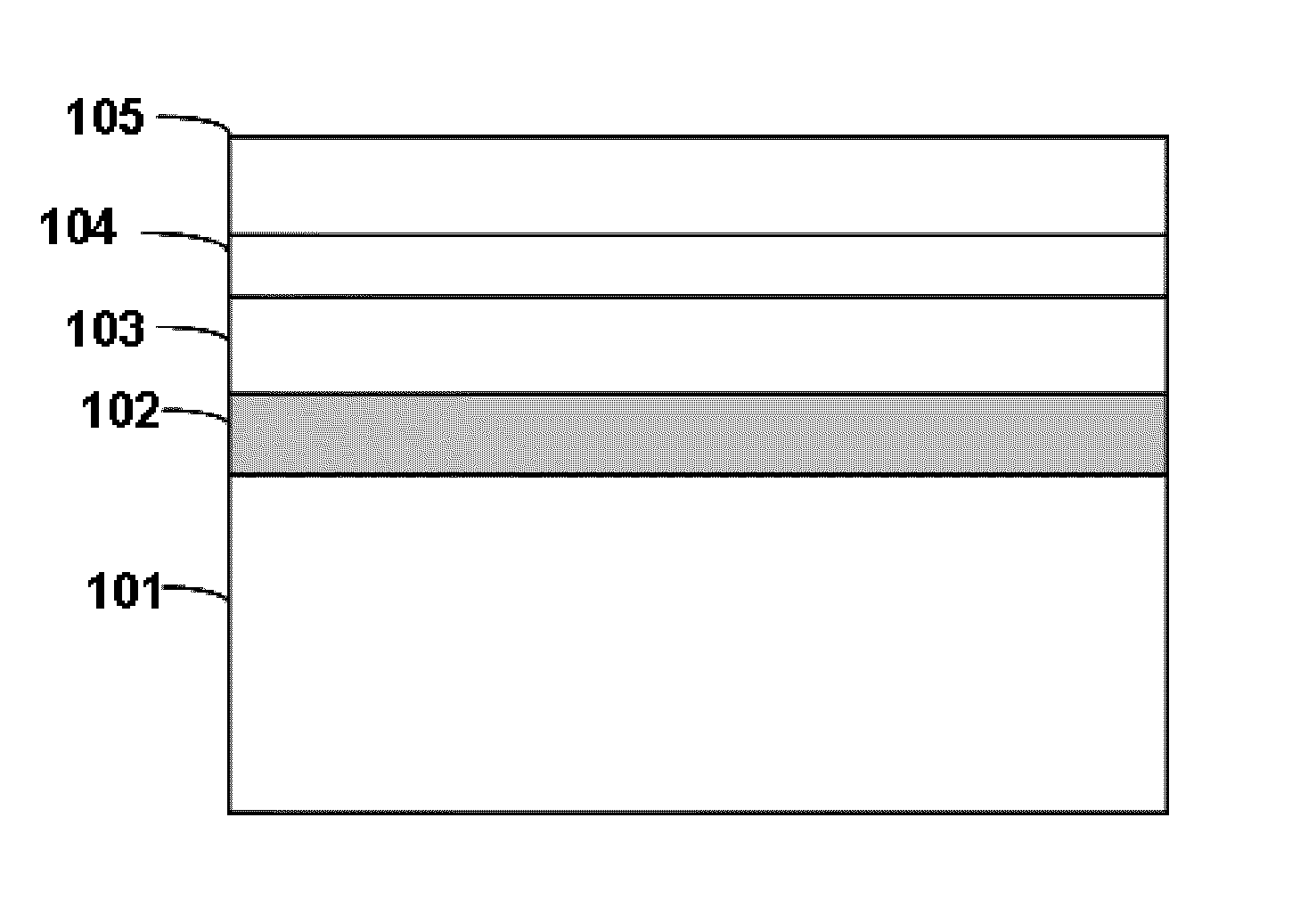
The present invention relates to a method that prevents oxygen from entering the interface layer of a device during the annealing process. This is achieved by forming a metal oxygen absorption layer on the gate electrode, which reduces the thickness of the SiO2 interface layer and effectively lowers the EOT (equivalent oxide thickness) of the device.

Problems solved by technology

If this thickness continues to reduce, the leakage current and the power consumption will increase dramatically, and problems like diffusion of doped boron atoms, polysilicon depletion effect, and extraordinarily high gate resistance caused by the polysilicon gate electrode, will become more and more serious.
Nevertheless, in the high-k metal gate process, the annealing process that must be adopted causes the interface layer to become thicker during the annealing process.
However, the CMOS device with feature size smaller than 45 nm has very serious short channel effect and a gate dielectric with an EOT (Equivalent Oxide Thickness) of not more than 1 nm is needed to better control of the channel, therefore a thick interface layer SiO2 would be unacceptable.

Method used


Image

  • Method of manufacturing a semiconductor device
  • Method of manufacturing a semiconductor device
  • Method of manufacturing a semiconductor device

Examples


Embodiment Construction

[0010]The present invention generally relates to a method of manufacturing a semiconductor device. The following disclosure provides many different embodiments or examples for realizing different structures of the present invention. To simplify the disclosure of the present invention, the components and configuration of specific examples are described in the following text. Of course, they are merely examples and are not intended to limit the invention. In addition, reference numerals and / or letters can be repeated in different examples in the present invention, and such repetition is for the purpose of concision and clarity, which in itself does not discuss the relationship between the various embodiments and / or configurations. Furthermore, the present invention provides examples of various specific techniques and materials, but those skilled in the art will be aware of the applicability of other techniques and / or materials. Moreover, the structure in which the first element is “ab...


PUM

PropertyMeasurementUnit
temperatureaaaaaaaaaa
thicknessaaaaaaaaaa
thicknessaaaaaaaaaa

Abstract

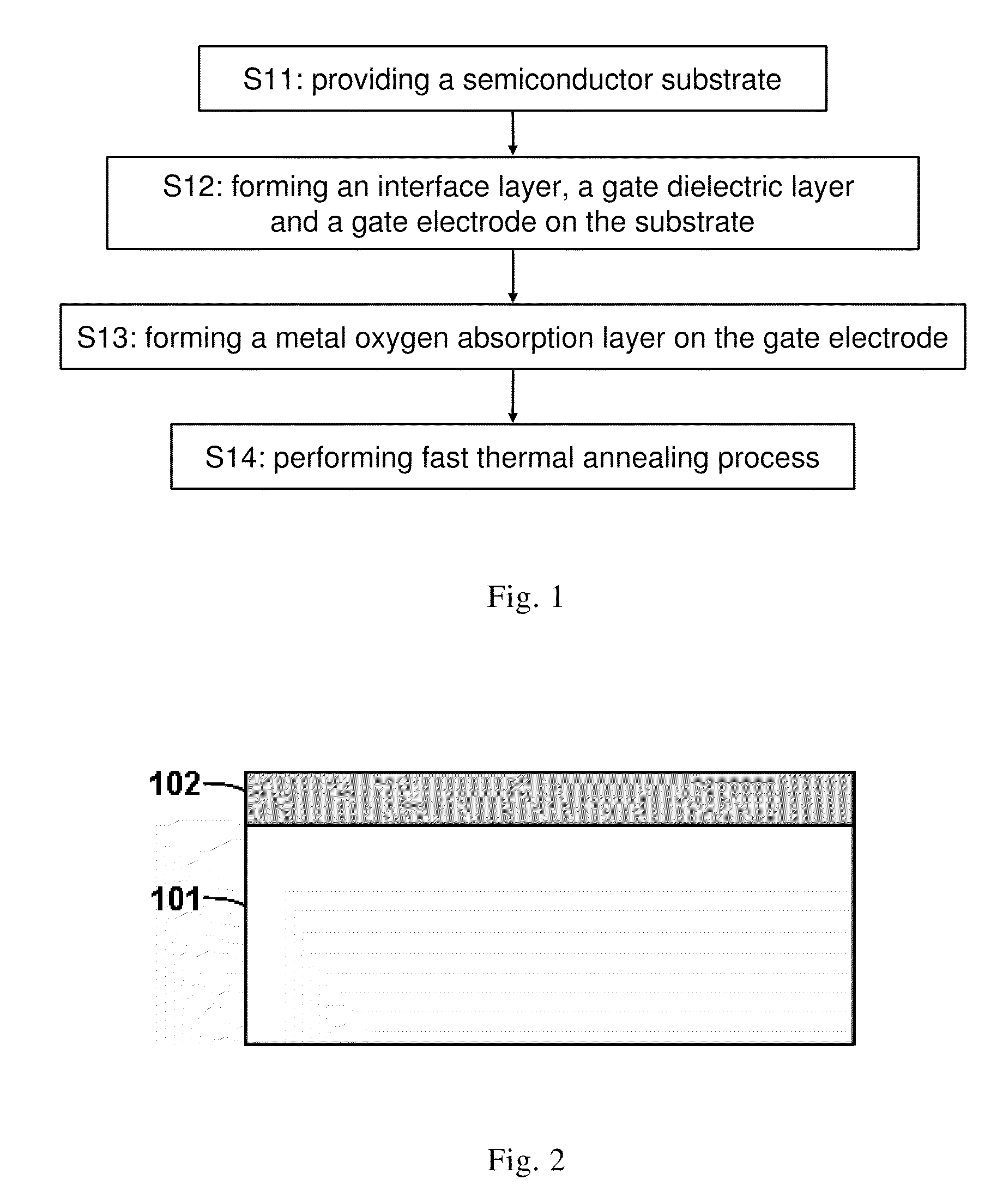
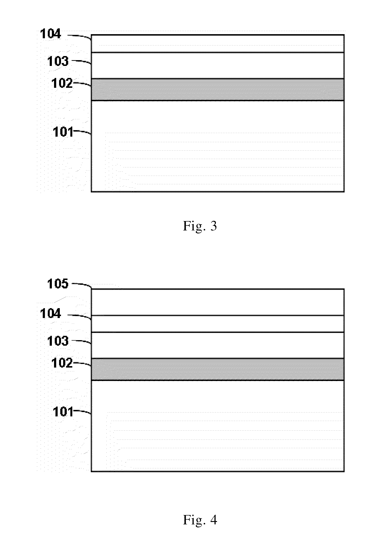
The present invention relates to the field of semiconductor manufacturing. The present invention provides a method of manufacturing a semiconductor device, which comprises: providing a semiconductor substrate; forming an interface layer, a gate dielectric layer and a gate electrode on the substrate; forming a metal oxygen absorption layer on the gate electrode; performing a thermal annealing process on the semiconductor device so that the metal oxygen absorption layer absorbs oxygen in the interface layer and the thickness of the interface layer is reduced. By means of the present invention, the thickness of the interface layer can be reduced on one hand, and on the other hand the metal in the metal oxygen absorption layer is made to diffuse into the gate electrode and / or the gate dielectric layer through the annealing process, which further achieves the effects of adjusting the effective work function and controlling the threshold voltage.

Description

BENEFIT CLAIMS[0001]This application is a US National Stage of International Application No. PCT / CN2010 / 077384, filed Sep. 28, 2010, which claims the benefit of CN 201010147605.5, filed Apr. 14, 2010.FIELD OF THE INVENTION[0002]The present invention generally relates to a method of manufacturing a semiconductor device, particularly to a method of manufacturing a high-k / metal gate semiconductor device that removes the oxygen atoms from the interface layer.DESCRIPTION OF THE PRIOR ART[0003]During decades of development of microelectronic technique, manufacturers of logic chips have always been employing SiO2 as the gate dielectric and employing heavily doped polysilicon as the material for gate electrodes when manufacturing MOS devices. However, with the ever-decreasing feature size, the gate dielectric of SiO2 in the MOS transistor has approximated to its limit. For example, in 65 nm process, the thickness of the SiO2 gate dielectric has been reduced to 1.2 nm, which is about the thi...

Claims


Application Information

Patent Timeline
Patent Type & Authority Patents(United States)
IPC IPC(8): H01L21/28
CPCH01L21/28176H01L29/517H01L29/4908H01L29/4966H01L29/513
Inventor HAN, KAIWANG, WENWUWANG, XIAOLEICHEN, SHIJIECHEN, DAPENG
Owner INST OF MICROELECTRONICS CHINESE ACAD OF SCI
Learn More