Method of operating an MRI imaging system, while also controlling graadient and shim sub-systems along with the MRI imaging system

a technology of graadient and shim sub-systems, which is applied in the field of magnetic resonance systems, can solve the problems of excessive time-consuming methods, high demands on control sequence developers, and inability to provide information or at best limited information about the occupation of space (i.e. position and orientation), and achieve the effect of increasing the quality of imaging methods and image data generated therewith

Active Publication Date: 2014-01-21
SIEMENS HEALTHCARE GMBH
View PDF34 Cites 8 Cited by
  • Summary
  • Abstract
  • Description
  • Claims
  • Application Information

AI Technical Summary

Benefits of technology

[0010]An object of the present invention is to further develop a method to control an imaging system as well as an imaging system such that the quality of the imaging method and of the image data generated therewith is increased without additional effort, or with as little additional effort as possible.
[0013]With this method it is thus ensured that all sub-sequences can always ensue optimized locally to the respective significant volume without complicated prior calculations by the operator being required for this purpose. An optimal image quality thus can be ensured in a particularly simple manner. For example, if an operator would like to modify a control protocol in order to use a somewhat different sub-sequence within a measurement sequence or in order to associate a different active volume with a specific sub-sequence, the operator can input the commands separate from one another or modify them in the control protocol, which is significantly simpler, safer and faster than if the operator must initially modify the sequence control data for the sub-sequence himself or herself so that these are optimized with regard to a different active volume.
[0014]An imaging system according to the invention requires a control device fashioned according to the invention. This control device must be able to automatically generate the control signals to implement the measurement sequence for the different subsystems based on sequence control data and based on separately received active volume position data so that the individual functional sub-sequences are locally optimized at least with regard to a sub-region of their associated active volume. The components that are required for this in the control device can advantageously be realized in the form of software modules on a processor or multiple processors of the control device that are networked among one another. Such a realization in software has the advantage that conventional imaging systems can also be retrofitted quickly and cost-effectively in the manner according to the invention. The invention therefore also encompasses a computer-readable storage medium that can be loaded directly into a memory of a programmable control device of an imaging system, and is encoded with program code segments in order to execute all steps of the method according to the invention that is described above when the program is executed in the control device.
[0018]With regard to the radio-frequency reception system, a dynamic selection of the acquisition coils for the current active volume can optimally ensue with regard to the signal-to-noise ratio (SNR) and / or according to iPAT criteria (a method to accelerate the image acquisition).

Problems solved by technology

In general, however, no information or at best limited information about the occupation in space (i.e. the position and orientation) and the extent of the different sub-volumes is provided to the technical subsystems.
However, all of these methods deal only with the setting of individual subsystems of the magnetic resonance system.
This method is extraordinarily time-consuming, and places markedly high demands on the developers of the control sequences.
A poorer optimization in turn leads to worse measurement results, which in the extreme case can lead to the situation that the generated images are not useful and a greater risk of misinterpretations exists, or measurements must be repeated, which causes additional stress for the patient.

Method used


Image

  • Method of operating an MRI imaging system, while also controlling graadient and shim sub-systems along with the MRI imaging system
  • Method of operating an MRI imaging system, while also controlling graadient and shim sub-systems along with the MRI imaging system
  • Method of operating an MRI imaging system, while also controlling graadient and shim sub-systems along with the MRI imaging system

Examples


Embodiment Construction

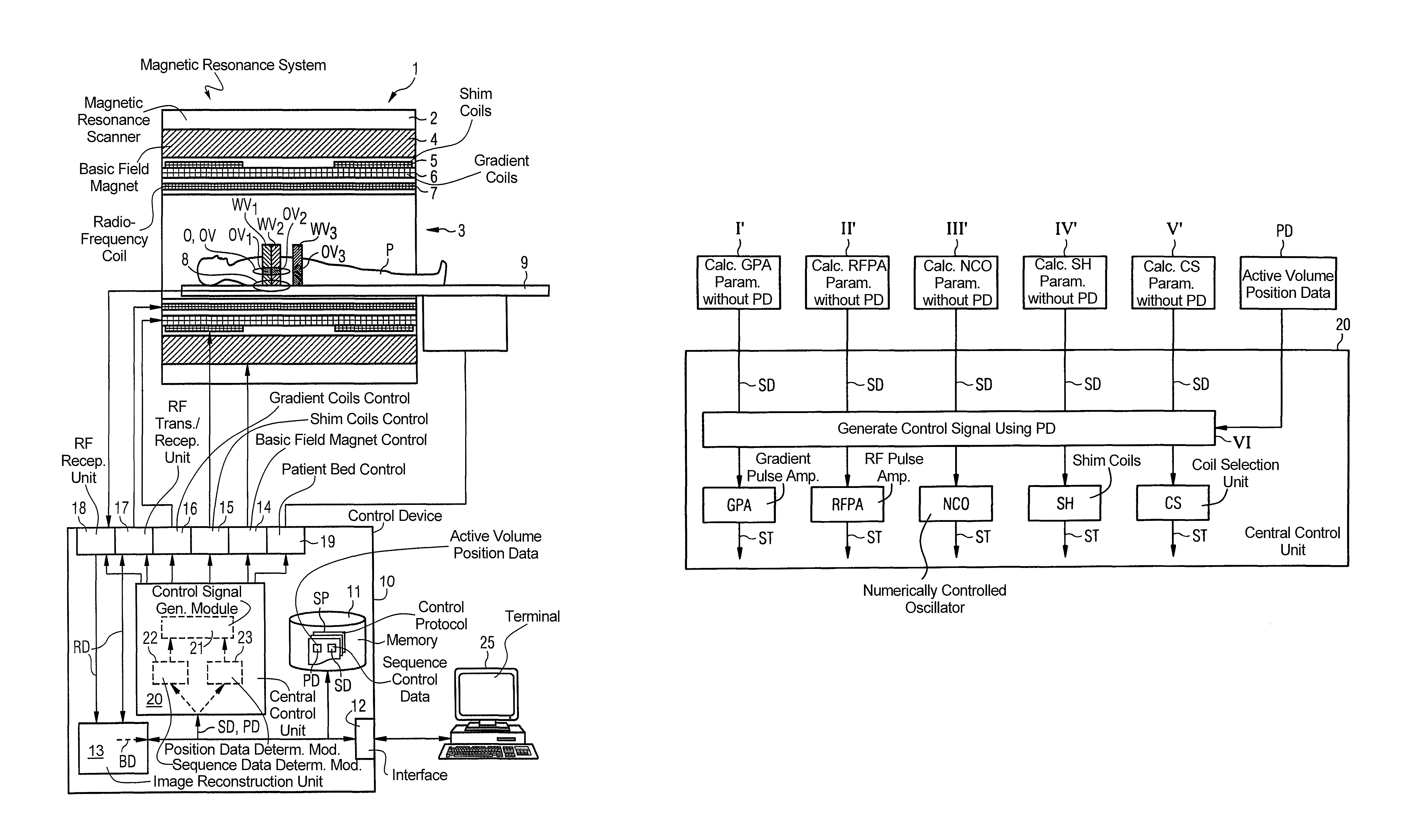
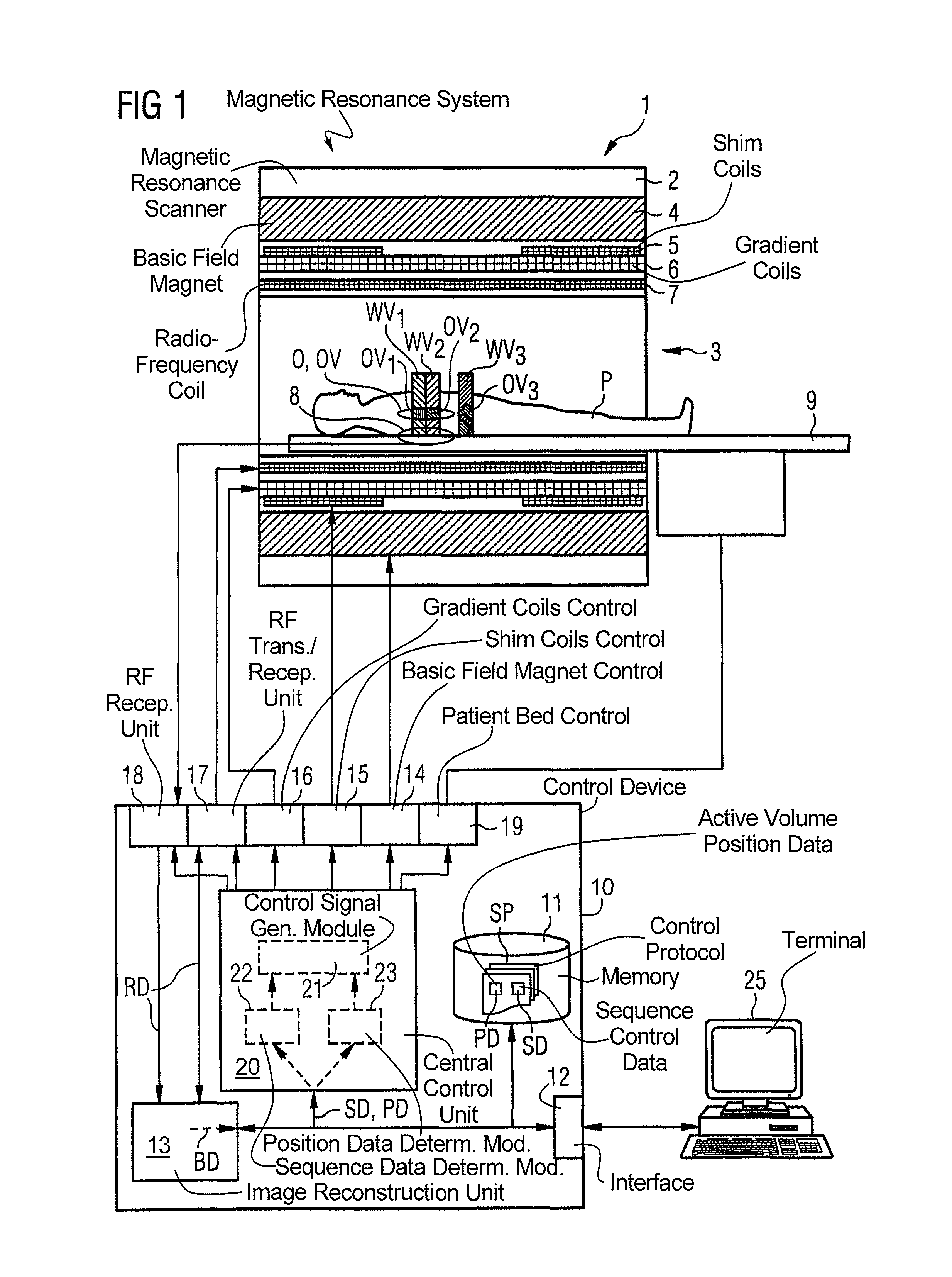
[0033]A magnetic resonance system 1 according to the invention is shown schematically in FIG. 1. It includes the actual magnetic resonance scanner 2 with an examination space 3 or patient tunnel located therein. A bed unit 9 can be driven into this patient tunnel 3 so that, during an examination, a patient P or test subject lying thereupon can be supported at a specific position within the magnetic resonance scanner 2 relative to the magnet system and radio-frequency system arranged in the magnetic resonance scanner 2, or can be moved between different positions during a measurement. At this point it is noted that the precise design of the magnetic resonance scanner 2 is not significant. For example, a cylindrical system with a typical patient tunnel can be used, as well as a C-arm-shaped magnetic resonance apparatus which is open to one side.

[0034]Basic components of the magnetic resonance scanner are a basic field magnet 4, a number of shim coils 5 and magnetic field gradient coil...


PUM


Abstract

In an imaging system having a number of subsystems and a control device that controls the subsystems in a coordinated manner to implement a measurement sequence and an operating method therefor, sequence control data that define different functional sub-sequences of the measurement sequence are transmitted to the control device. Different active volumes are associated with the functional sub-sequences. In addition to the sequence control data, active volume position data are provided to the control device that define bearing and extent of the active volumes associated with the different functional sub-sequences. Control signals to implement the measurement sequence for the different subsystems are generated automatically by the control device based on the sequence control data and the active volume position data so that the individual functional sub-sequences are locally optimized at least with regard to a sub-region of their associated active volume.

Description

BACKGROUND OF THE INVENTION[0001]1. Field of the Invention[0002]The present invention concerns a method to operate an imaging system, in particular a magnetic resonance system, with a number of subsystems and a control device that controls the subsystems in a coordinated manner to implement a measurement sequence. For this sequence control data which define different functional sub-sequences of the measurement sequence are provided to the control device, wherein different active volumes are associated with the functional sub-sequences. Moreover, the invention concerns an imaging system with a number of subsystems and a control device to implement this method.[0003]2. Description of the Prior Art[0004]Tomographical imaging systems (for example magnetic resonance apparatuses or computed tomography systems) are complex installations with multiple technical subsystems. Among these (for example in a magnetic resonance system) are the basic field magnet system in order to expose a body to...

Claims


Application Information

Patent Timeline
Patent Type & Authority Patents(United States)
IPC IPC(8): G01R33/54A61B5/055
CPCG01R33/54G01R33/546A61B5/055
Inventor FEIWEIER, THORSTENFISCHER, DANIELJESCHKE, HENDRIKSPECKNER, THORSTENSTOECKER, STEPHAN
Owner SIEMENS HEALTHCARE GMBH
Why Eureka
Try Eureka