Humidifier with internal heating element and heater plate

a technology of heater plate and heater element, which is applied in the direction of lighting and heating apparatus, combustion-air/fuel-air treatment, combustion types, etc., can solve the problems of increasing discomfort, increasing weight, inflaming and inflaming areas, etc., and achieves the effect of preventing collapse, effective and sa

Active Publication Date: 2014-01-28
FISHER & PAYKEL HEALTHCARE LTD
View PDF8 Cites 7 Cited by
  • Summary
  • Abstract
  • Description
  • Claims
  • Application Information

AI Technical Summary

Benefits of technology

[0026]It is an object of the present invention to provide a breathing assistance apparatus which goes some way to overcoming the abovementioned disadvantages or which at least provides the public or industry with a useful choice.

Problems solved by technology

One of the side effects of CPAP therapy is that the stream of air can dry the nasal membranes, or the mouth and throat membranes of a user.
This can lead to these areas becoming inflamed and uncomfortable.
Although systems exist that locate the humidifier close to the user, this arrangement tends to add weight close to the patient, and can increase their discomfort and decrease the usability of the system.
There are several disadvantages when using prior art systems of the type described above where the humidification chamber is located remotely from the patient.
However, there is no guarantee that the gases leaving such humidifiers are in fact 100% saturated.
Typically, humidification systems are only controlled to achieve a desired outlet gas temperature (not humidity).Intermittent or varying flow rates (caused for example by fluctuating demand from the user's breathing) will cause the humidity of the gas passing out from the humidity chamber to be uneven.
It is not possible to compensate for varying flow rates by varying the inputs, e.g. varying heater power.It is usual for humidifiers of the prior art type to be heated from the base.
This arrangement can be inefficient If air or gas enters the chamber at a lower temperature than the water and the saturated vapour in the chamber, it is likely that the gas will exit the chamber in a state where it is not fully saturated (not in a state of absolute humidity).
However, these gases can lose heat energy as they travel from the pre-heater to the humidification chamber.
It is usually not possible to retrofit a pre-heater in an existing blower unit.
This can be expensive.
The partition wall allows water vapour or humidified gas to pass through from the water reservoir to the humidification enclosure, but does not allow liquid water or water in droplet form to pass through.

Method used


Image

  • Humidifier with internal heating element and heater plate
  • Humidifier with internal heating element and heater plate
  • Humidifier with internal heating element and heater plate

Examples


Embodiment Construction

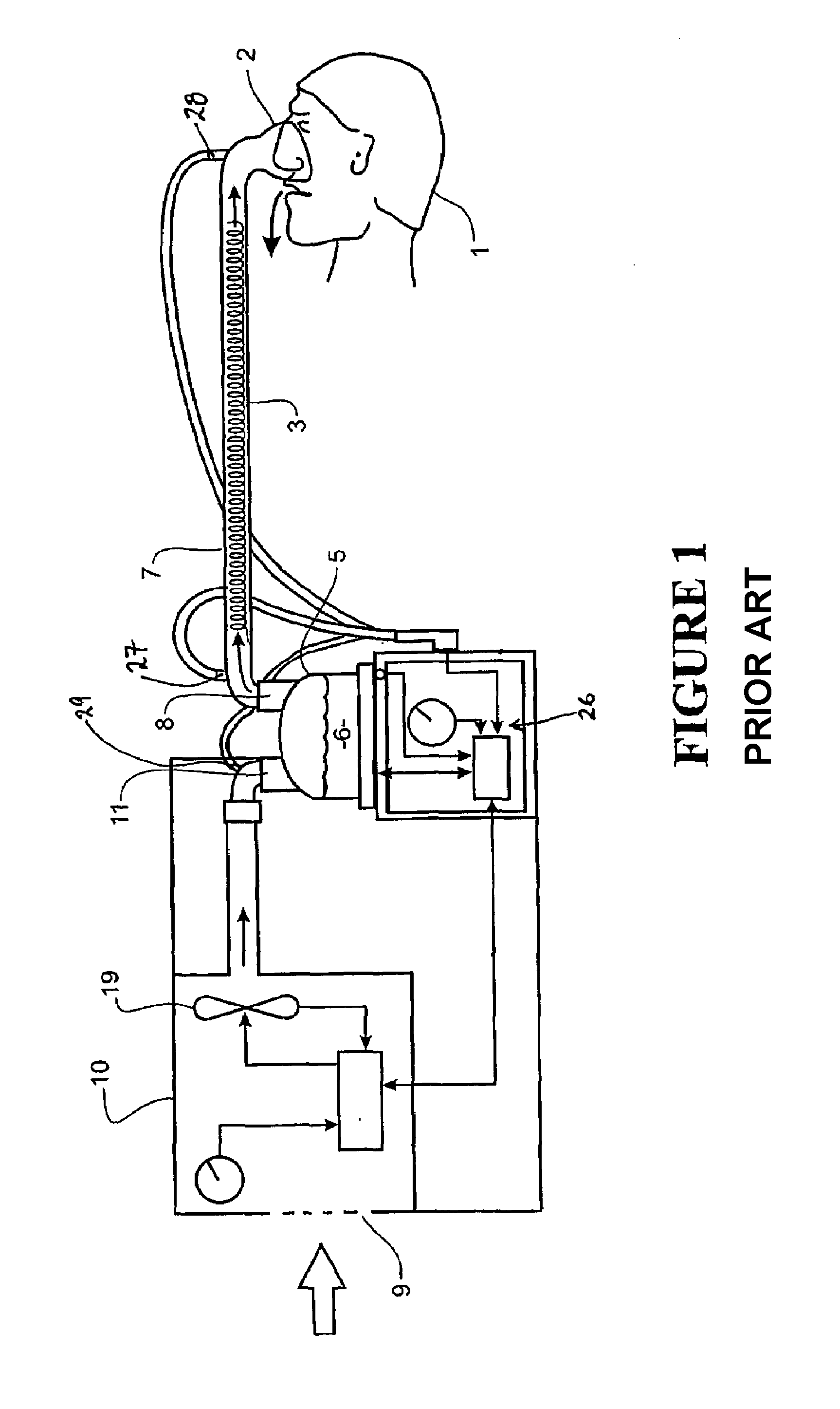
[0060]The present invention provides a humidification chamber for use with a breathing assistance apparatus where the flow of gases to a user passes in sequence through a gases supply device or flow driver (a blower, fan or compressor unit), the humidification chamber, a heated delivery conduit and a patient interface, similar to that outlined in the prior art section above. The present invention also provides a breathing assistance apparatus that includes the humidification chamber.

[0061]The preferred form of the humidifier chamber of the present invention can be used with the system described above, in place of the chamber 5, or the chamber could be used with any other suitable breathing assistance apparatus.

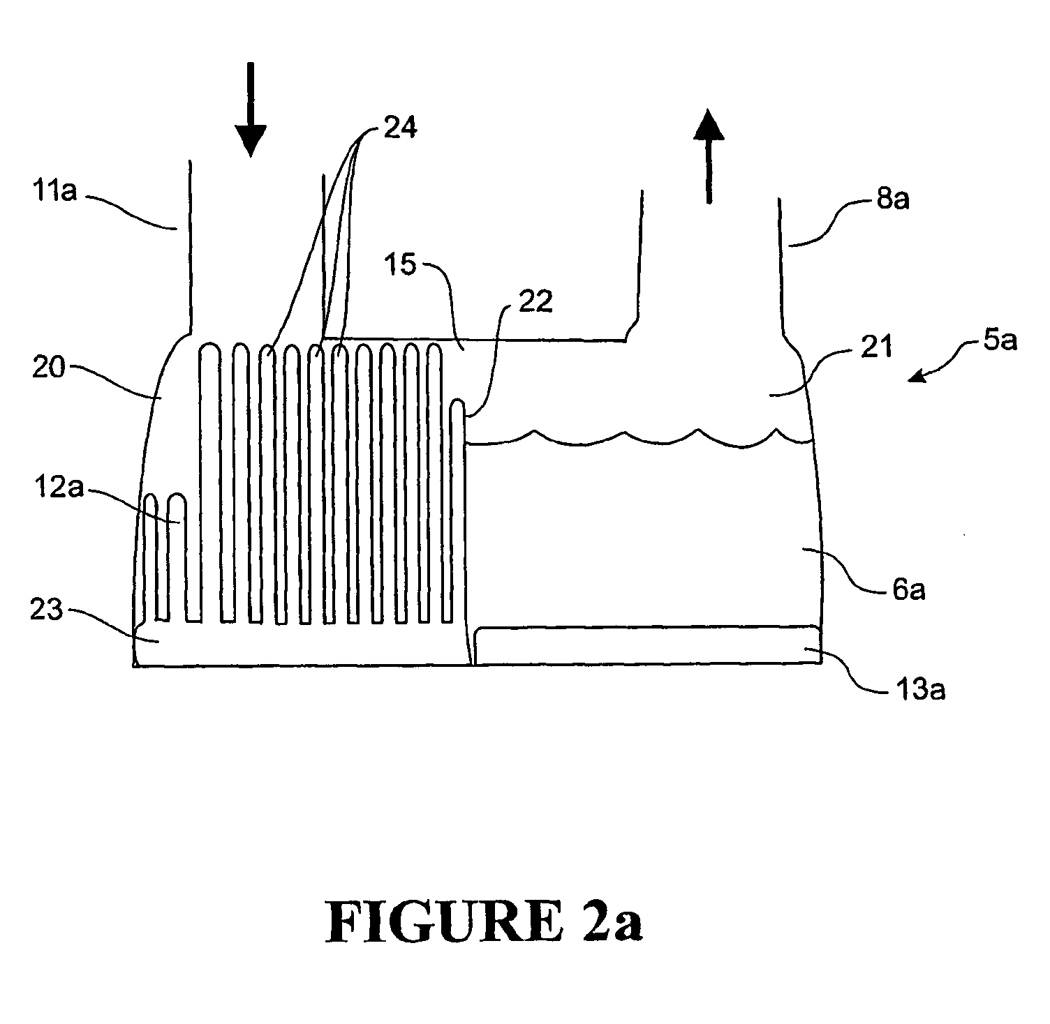
[0062]The preferred form of the humidifier chamber will now be described with reference to FIGS. 2 to 5.

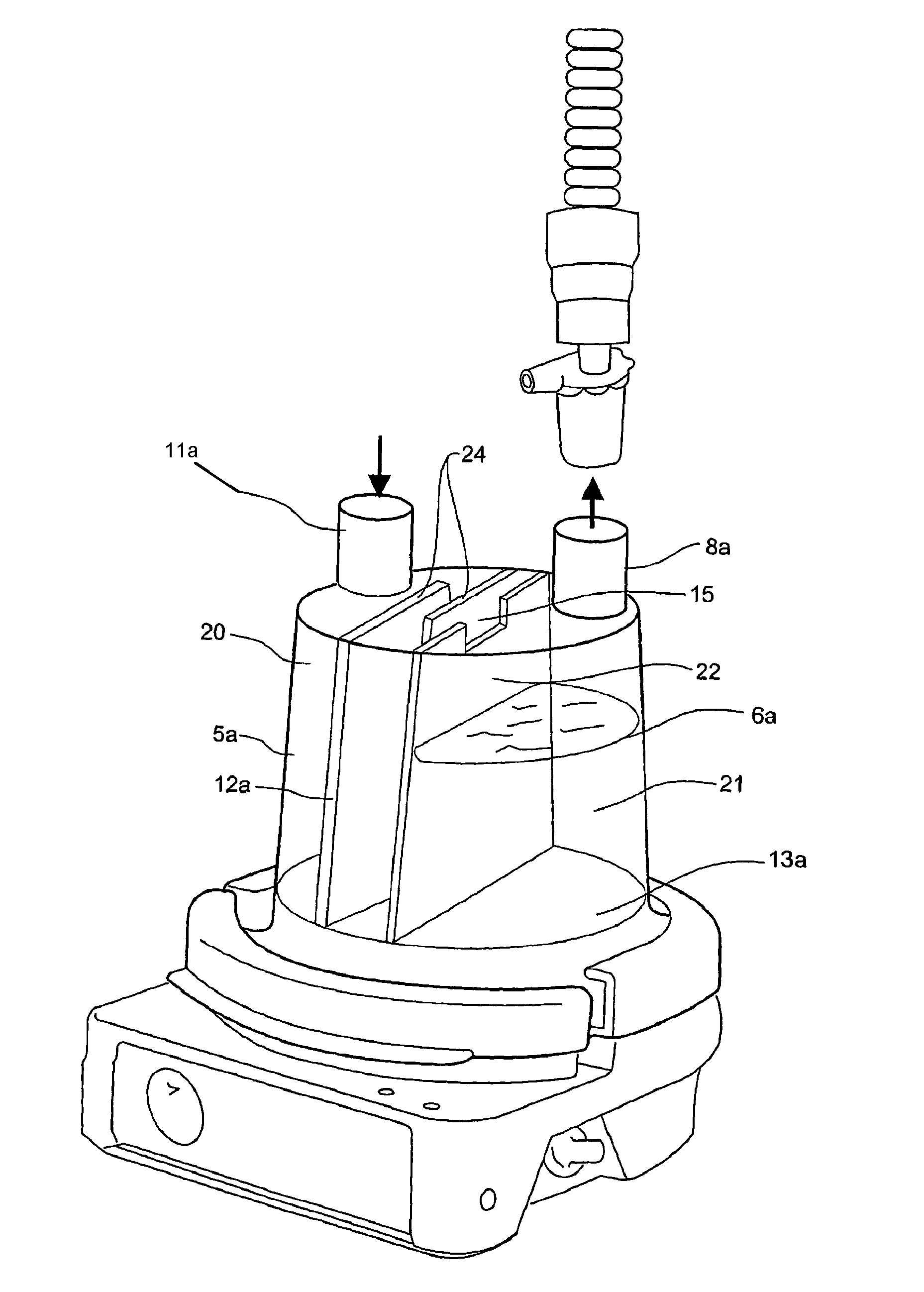
[0063]FIG. 2a shows a humidifier chamber 5a with an inlet port 11a and an outlet port 8a. The chamber 5a has a base 13a and in use is connected to a housing such as housing ...


PUM


Abstract

A respiratory humidifier chamber for use with a breathing assistance apparatus is described. The chamber includes a water-tight vessel having an inlet for receiving gases from the breathing assistance apparatus, and an outlet through which heated humidified gases exit the vessel for delivery to a patient. The chamber has a partition which divides the chamber into upstream and downstream sub-chambers. The sub-chambers are separated by the partition except for an aperture which passes through the partition and allows gaseous communication between the sub-chambers. The downstream sub-chamber includes a heater base which heats a volume of water contained within it. The aperture is located above the volume of water. The upstream sub-chamber contains an internal heater which heats gases passing through it from the inlet to the aperture. At least part of the internal heater is located immediately adjacent the aperture.

Description

[0001]This application is a National Phase filing of PCT / NZ2007 / 000228, having an International filing date of Aug. 24, 2006, which disclosure is herein incorporated by reference.BACKGROUND OF THE INVENTION[0002]1. Field of the Invention[0003]This invention relates to a gases supply and gases humidification apparatus, particularly, but not solely, for providing respiratory assistance to patients or users who require a supply of gas at positive pressure for the treatment of diseases such as Obstructive Sleep Apnea (OSA), snoring or Chronic Obstructive Pulmonary Disease (COPD) and the like. In particular, this invention relates to a humidifier chamber for use in a gases supply apparatus.[0004]2. Summary of the Prior Art[0005]A number of methods are known in the art for supplying humidified gases to a patient to assist a patient's breathing. Continuous Positive Airway Pressure (CPAP) involves the administration of air under pressure to a patient, usually by passing gases to the patient...

Claims


Application Information

Patent Timeline
Patent Type & Authority Patents(United States)
IPC IPC(8): F23D11/00F23D14/00
CPCA61M16/1075A61M16/16A61M2016/109A61M16/109A61M16/161A61M16/024
Inventor MCAULEY, ALASTAIR EDWINLO, RAYMOND KA YAUWIXEY, DAVID FRASERMAKINSON, IAN DOUGLAS
Owner FISHER & PAYKEL HEALTHCARE LTD
Why Eureka
Try Eureka