Charged particle analysers and methods of separating charged particles

a technology of charged particles and analysers, which is applied in the direction of particle separator tube details, tube electrostatic deflection, separation process, etc., can solve the problems of increasing manufacturing costs, requiring more laboratory space for housing instruments, and extending the size of instruments, so as to achieve the effect of keeping the length of the internal ejection trajectory preferably short and avoiding the length of the internal ejection trajectory

Active Publication Date: 2014-01-28
THERMO FISHER SCI BREMEN
View PDF31 Cites 34 Cited by
  • Summary
  • Abstract
  • Description
  • Claims
  • Application Information

AI Technical Summary

Benefits of technology

[0056]Preferably, the beam undergoes at least one oscillation of substantially simple harmonic motion in the direction of the z axis as it reflects from one mirror to the other.
[0436]Some embodiments of the present invention benefit from the further advantage that charged particles are transported through the TOF analyser coherently, enabling TOF imaging to be performed, or allowing a beam of charged particles comprising multiple beams from different starting locations to be sent through the analyser, overlapping in time, but following different paths to arrive at different locations at a detector plane, thereby increasing the throughput of the analyser. The detector plane may be flat or curved. A detection system may be employed to either image the charged particles or provide detection facilities at locations where the different multiple beams of charged particles will arrive. In both cases the detection system distinguishes between charged particles that started from different locations. This characteristic provides immediate application for MALDI sources but is not so limited.

Problems solved by technology

However, increases in a simple linear path length lead to an enlarged instrument size, increasing manufacturing cost and requiring more laboratory space to house the instrument.
However, reflecting time of flight geometries that produce a folded path and multiple sector designs have the disadvantage that they require multiple high-tolerance ion optical components, adding cost and complexity, as well as generally being larger in size.
Some reflectors having improved time focusing for particles of differing energies include grids to better control the electric field within the reflector, however such reflectors are less suitable for multi-reflection systems, as ions are lost through collisions with the grids at each reflection, and the overall transmission of the system after multiple reflections is compromised.
Difficulties exist with the use of such parabolic potential reflectors, however, as they tend to produce strong divergence of ion beams in directions orthogonal to the axis of reflection.
This makes 2 or more reflections in such mirrors simply impractical.
The quality of focusing in such fields also degrades as longer field-free regions are introduced between an ion source and entrance to such a mirror.
The use of multiple reflectors or multiple sectors requires sophisticated design and high tolerance manufacturing for each of the several reflectors or sectors, resulting in increased complexity and cost, as well as typically a larger instrument size.
However, such lenses themselves cause beam aberrations unless they are quite weak and can limit the quality of the final time focus and hence limit mass resolution.
More importantly in practice, the substantial non-linearity of the reflecting field even near the turning points in all mirrors of this type drastically reduces the tolerance to space charge, as described in WO06129109.
Both these single reflecting TOF instruments have limited mass resolution, the latter demonstrating only a resolving power of 40.
The main problem with these systems relates to the precise definition of the field, especially at the points of ion injection and ejection.
This problem stems from the necessity to avoid any field-free drift spaces within such a system in order to have axial field strictly linear along the entire ion path.

Method used


Image

  • Charged particle analysers and methods of separating charged particles
  • Charged particle analysers and methods of separating charged particles
  • Charged particle analysers and methods of separating charged particles

Examples


Embodiment Construction

[0450]In order to more fully understand the invention, various embodiments of the invention will now be described by way of examples only and with reference to the Figures. The embodiments described are not limiting on the scope of the invention.

DESCRIPTION OF FIGURES

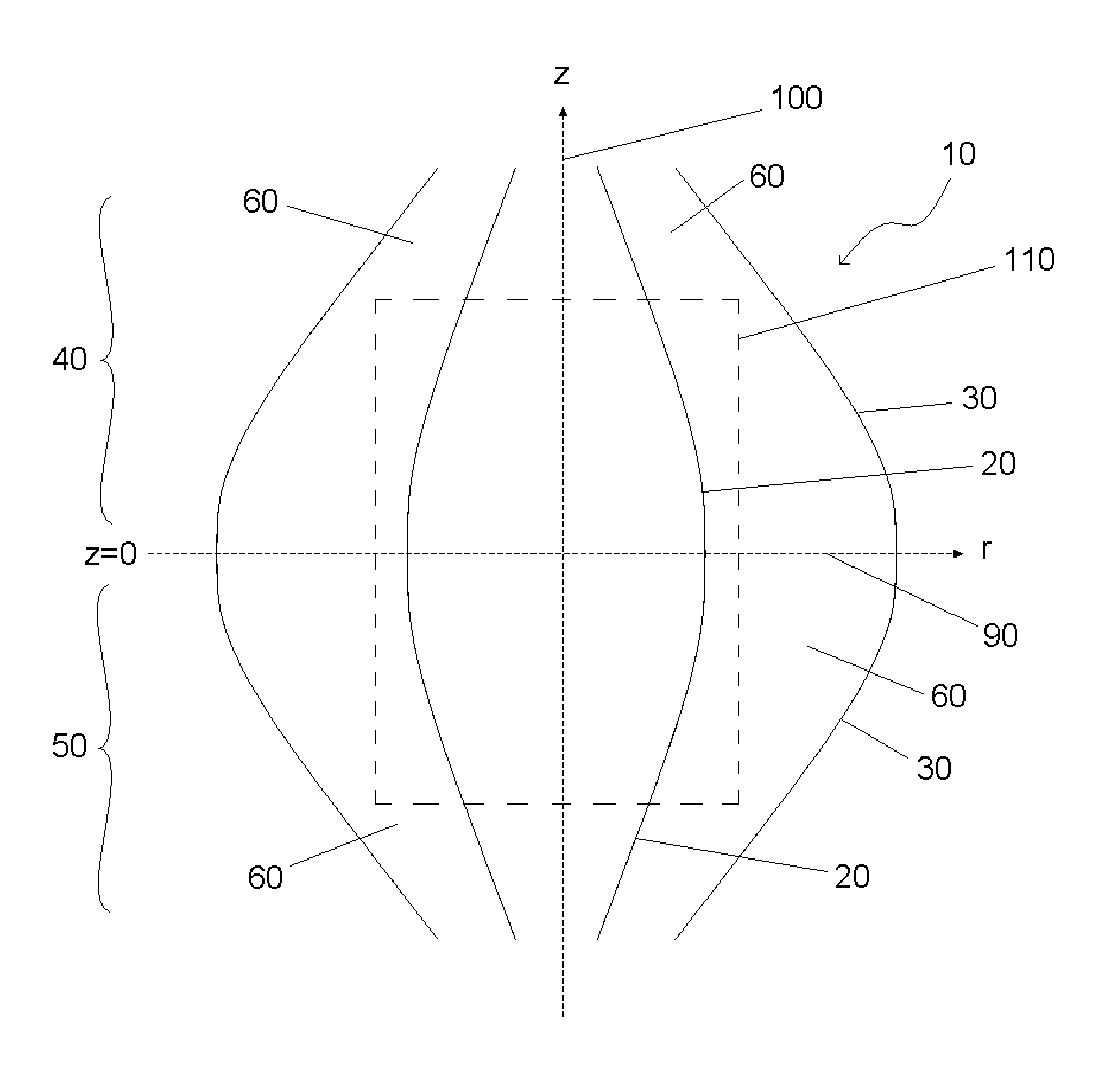
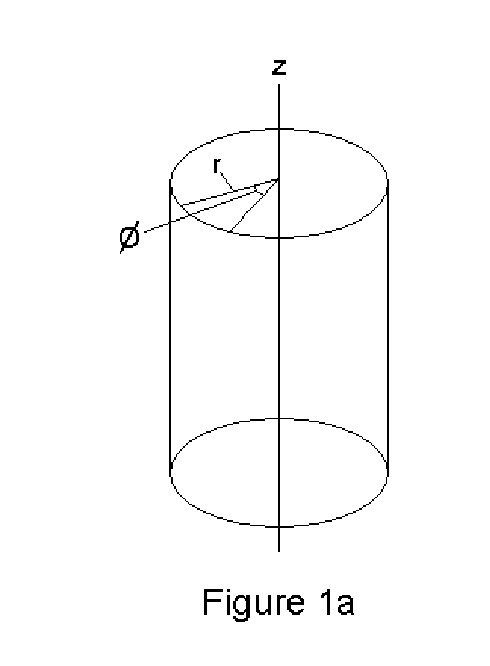
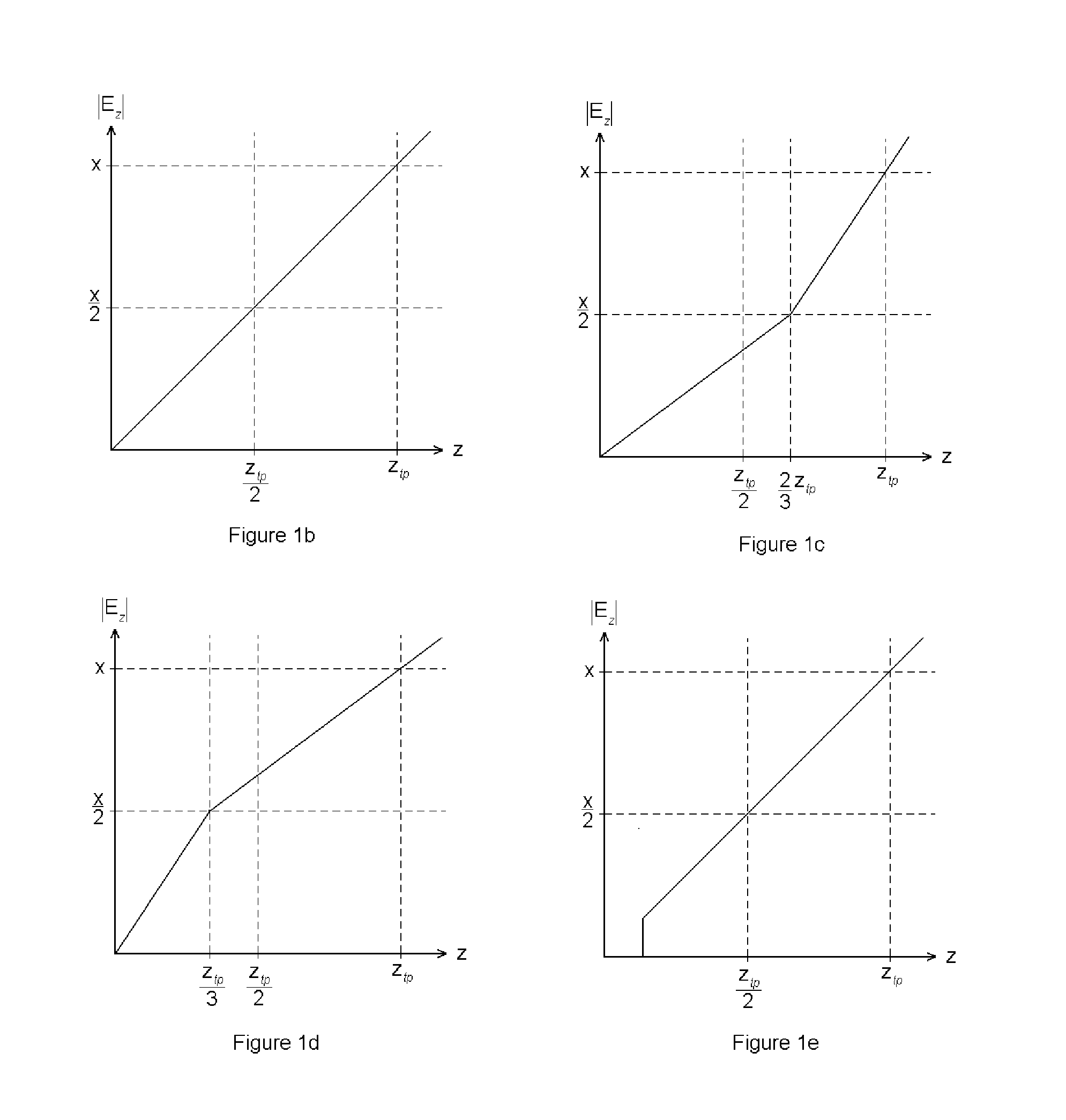
[0451]FIG. 1 shows the coordinate system used to describe features of the present invention and the z dependence of the of the electric field strength.

[0452]FIG. 2 shows schematic views of the electrode structures for various embodiments of the invention.

[0453]FIG. 3 shows schematically examples of main flight paths of the beam in embodiments of the invention and its envelopes.

[0454]FIG. 4 shows schematic representations of a beam of ions undergoing oscillations in an analyser according to the invention with (FIG. 4b,c) and without (FIG. 4a) arcuate focusing lenses, and an example of an arcuate focusing lens.

[0455]FIG. 5 shows schematically various embodiments of arcuate focusing lenses of the invention and a schematic ...


PUM


Abstract

Methods and analysers useful for time of flight mass spectrometry are provided. A method of separating charged particles comprises the steps of: providing an analyser comprising two opposing mirrors each mirror comprising inner and outer field-defining electrode systems elongated along an axis z, the outer system surrounding the inner and defining therebetween an analyser volume, the mirrors creating an electrical field within the analyser volume comprising opposing electrical fields along z, the strength along z of the electrical field being a minimum at a plane z=0; causing a beam of charged particles to fly through the analyser, orbiting around the z axis within the analyser volume, reflecting from one mirror to the other at least once thereby defining a maximum turning point within a mirror; the strength along z of the electrical field at the maximum turning point being X and the absolute strength along z of the electrical field being less than |X| / 2 for not more than ⅔ of the distance along z between the plane z=0 and the maximum turning point in each mirror; separating the charged particles according to their flight times; and ejecting at least some of the charged particles having a plurality of m / z from the analyser or detecting the at least some of charged particles having a plurality of m / z, the ejecting or detecting being performed after the particles have undergone the same number of orbits around the axis z.

Description

[0001]This application claims priority from UK application No. 0909232.1 filed on May 29, 2009. This application is a 371 of international application no. PCT / EP10 / 57340 filed on May 27, 2010.FIELD OF THE INVENTION[0002]This invention relates to charged particle analysers and methods of separating and analysing charged particles, for example using time of flight mass spectrometry.BACKGROUND[0003]Time of flight (TOF) mass spectrometers are widely used to determine the mass to charge ratio of charged particles on the basis of their flight time along a path. The charged particles, usually ions, are emitted from a pulsed source in the form of a packet, and are directed along a prescribed flight path through an evacuated space to impinge upon or pass through a detector. In its simplest form, the path follows a straight line and in this case ions leaving the source with a constant kinetic energy reach the detector after a time which depends upon their mass, more massive ions being slower....

Claims


Application Information

Patent Timeline
Patent Type & Authority Patents(United States)
IPC IPC(8): H01J49/40
CPCH01J49/4245H01J49/406H01J49/06H01J49/067H01J49/22H01J49/40
Inventor MAKAROV, ALEXANDER A.GIANNAKOPULOS, ANASTASSIOS
Owner THERMO FISHER SCI BREMEN
Why Eureka
Try Eureka