
Method of determining a magnet arrangement

a technology of arrangement and magnet, applied in the direction of magnetic circuit shape/form/construction, magnetic circuit rotating parts, electric generator control, etc., can solve the problems of shortening the life of the machine, affecting the overall efficiency, and affecting the operation of the motor and the generator. the effect of optimisation of the performance of the machine is much simpler and faster to carry out, and only a few performance parameters are minimised

Inactive Publication Date: 2014-02-04
SIEMENS AG
View PDF9 Cites 1 Cited by
  • Summary
  • Abstract
  • Description
  • Claims
  • Application Information

AI Technical Summary

Benefits of technology

This approach allows for a straightforward optimization of electrical machine performance, reducing losses, noise, and fatigue, enabling more efficient and reliable operation with reduced computational complexity and production costs.

Problems solved by technology

For various known reasons, electrical motors and generators cannot operate perfectly, and several factors can detract from the overall efficiency.
Since this force must be overcome at start-up and many times during each rotation of the rotor, it can have a large impact on the performance of the generator, shortening its lifespan and increasing its noise level.
Another problem is presented by torque ripple, which is the sum of cogging torque and the additional torque variations caused by harmonics in the air gap flux of the machine.
However, torque ripple can still have a detrimental impact on the efficiency, life time and noise level of the generator.
However, the known approaches are quite complicated.
However, the improvement will only be ideal for a given rotor position for each stator tooth.
However, simulation of a pattern of shifted poles is very cost-intensive, since, according to a rule of thumb, the computation time increases exponentially with increasing poles, so that patterns containing many poles result in very long computation times.
For example, if cogging is minimised, it is not possible to minimise ripple at the same time.
Another important consideration is that pole shifting will always result in a reduction in back emf (electromotive force) and running torque, which is usually a drawback, and the extent of the influence depends on the chosen pole shifting pattern.
However, the iron generally used for the stator and other parts is quite saturated, making the equations very nonlinear and complex.
The more variables are altered in striving for an optimal solution, the more complicated the analysis becomes.
Factors such as manufacturing tolerances such as eccentricity can result in real-life performance that does not fulfil the (simulated) expectations, since the modelled geometry is considerably different from the actual manufactured machine.
In approaches based on pole-shifting many magnets with respect to each other, a minor ‘error’ in the machine geometry can easily negate the benefits of the pole-shifting.

Method used


Image

  • Method of determining a magnet arrangement
  • Method of determining a magnet arrangement
  • Method of determining a magnet arrangement

Examples


Embodiment Construction

[0031]In the drawings, like reference numbers refer to like objects throughout. Objects in the diagrams are not necessarily drawn to scale.

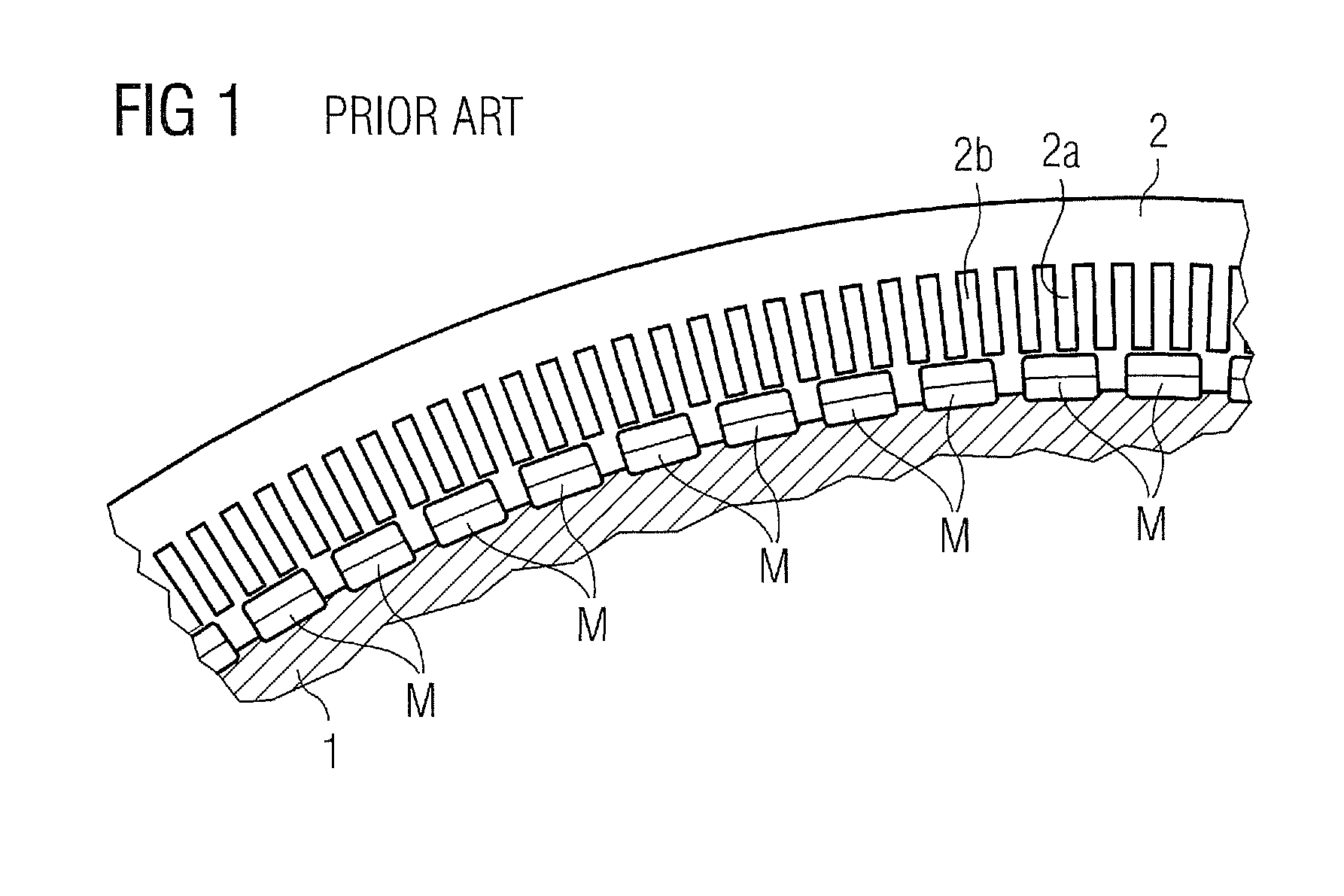
[0032]FIG. 1 shows a very simplified cross-section through an electrical generator 3, showing a rotor 1 and a stator 2, and a number of magnets M arranged on the rotor 1. In a conventional, simple arrangement, the magnets M are all spaced at equal distances from one another. The stator 2 comprises a plurality of teeth 2a defining a plurality of slots 2b for accommodating the stator windings (not shown). The stator 2 and therefore also the stator teeth 2a are generally made of steel so that, during operation, a magnetic force acts between the magnets M and the stator teeth 2a, known as cogging torque.

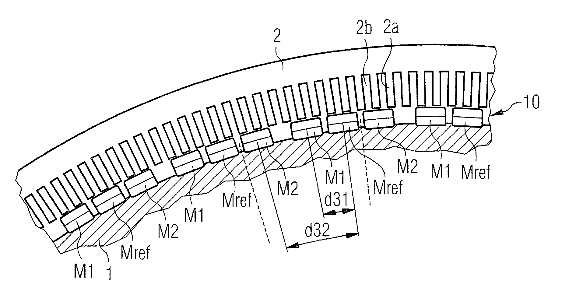
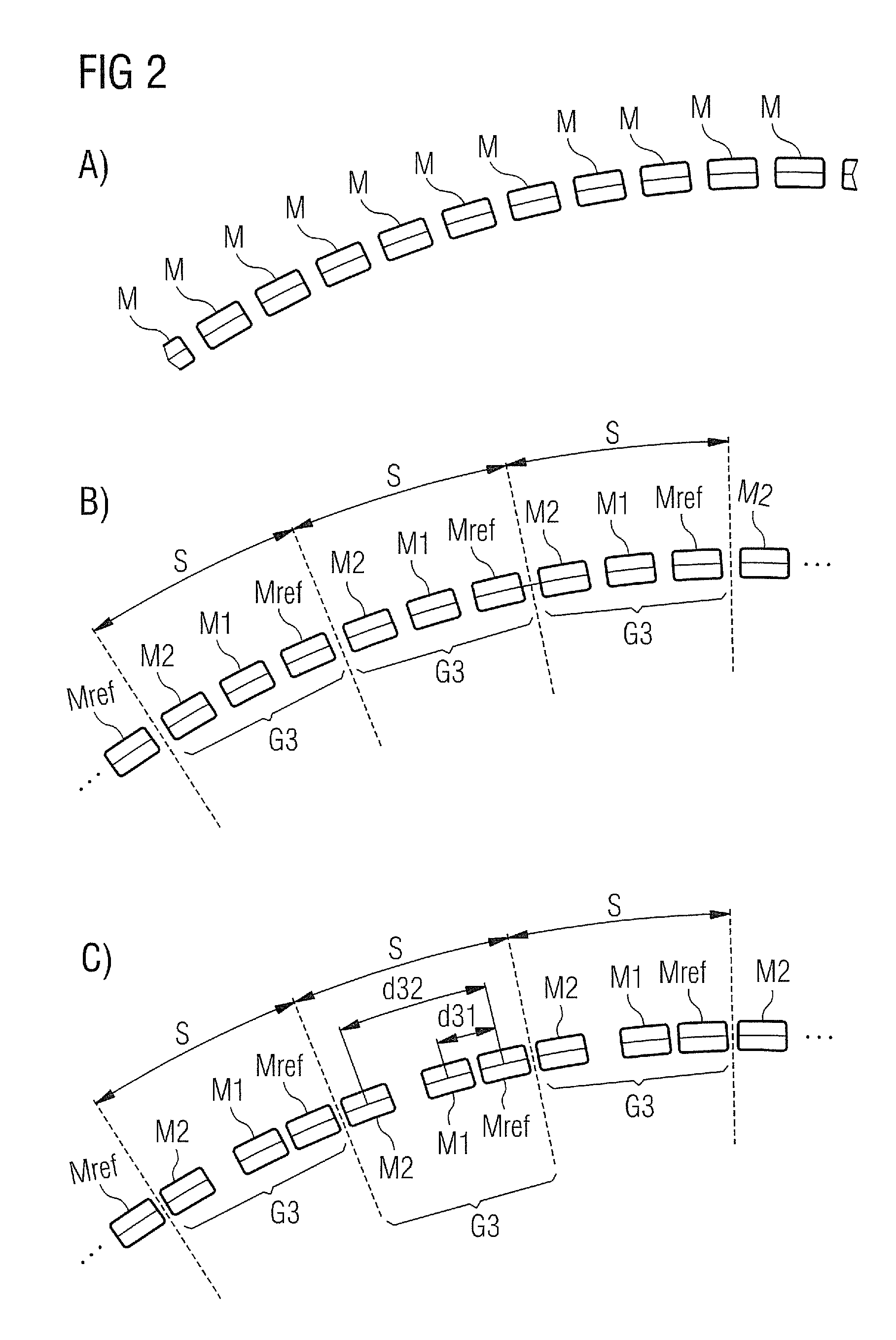
[0033]FIG. 2 illustrates some of the steps taken to arrive at a first magnet arrangement 10 according to the invention for two performance parameters of an electrical generator. Firstly, the magnets M, shown in part A of the diagram to be initially eq...


PUM


Abstract

A method for arranging magnets of a rotor or stator of an electrical machine is provided. In this method a number of performance parameters of the electrical machine are identified. A plurality of neighboring magnets are assigned to a magnet group. The magnet group includes a reference magnet and at least one further magnet. Further, a number of distinct magnet arrangement variables for the magnet group are identified, such that the number of arrangement variables is equal to the number of performance parameters. A value of an arrangement variable is calculated according to a desired adjustment of a performance parameter. Based on the calculated arrangement variable, an arrangement is determined for one of the at least one further magnet of the magnet group relative to the reference magnet of that magnet group.

Description

CROSS REFERENCE TO RELATED APPLICATIONS[0001]This application claims priority of European Patent Office application No. 10179461.8 EP filed Sep. 24, 2010, which is incorporated by reference herein in its entirety.FIELD OF INVENTION[0002]The invention describes a method of determining a magnet arrangement for the magnets of an electrical machine. The invention further describes a method of arranging a plurality of magnets of an electrical machine. The invention also describes a wind turbine with a generator and a plurality of magnets arranged in such a magnet arrangement.BACKGROUND OF INVENTION[0003]For various known reasons, electrical motors and generators cannot operate perfectly, and several factors can detract from the overall efficiency. For example, cogging torque is caused by the magnetic attraction between the magnets of the rotor and the stator slots or stator teeth. In a homogenous arrangement in which the magnets / stator slots are all placed equidistantly, for a certain po...

Claims


Application Information

Patent Timeline
Patent Type & Authority Patents(United States)
IPC IPC(8): F03D9/00
CPCH02K2213/03H02K2213/12Y02E10/725H02K7/1838H02K1/278H02K29/03H02K1/17H02K15/03Y02E10/72H02K1/27
Inventor ANDERSEN, KURTGROENDAHL, ERIKPEDERSEN, KENNETH
Owner SIEMENS AG
Learn More