Multi-domain secure computer system

a computer system and multi-domain technology, applied in the field of computer systems, can solve the problems of not meeting the security standards, not providing the required protection from emf, and not offering a multi-domain computer system, so as to facilitate the access to the internal components of the chassis

Active Publication Date: 2014-02-04
SECUTOR SYST
View PDF26 Cites 71 Cited by
  • Summary
  • Abstract
  • Description
  • Claims
  • Application Information

AI Technical Summary

Benefits of technology

[0024]The chassis may be constructed so that it is divided into isolated, shielded compartments or chambers established as separate Faraday cages. Each computer shall be housed in its own chamber / compartment that is a Faraday Cage. The chambers will thus wrap each computer domain in total, on all six sides or walls of the chamber volume. These six walls form an effective EMF shield, with the walls configured so as to eliminate slot antenna effects along the seams of the walls. In this way, a Faraday cage (where EMF energy produced by each isolated computer), does not impact the operation of the other computers that reside within the chassis, nor can the operation of one computer be “heard” from the chamber in which another computer is hosted. The properties of the material used to construct the chassis and the design of chambers in regards to EMF propagation, prevent the passage of any significant EMF energy between each chamber within the chassis.
[0045]The first computer domain, the second computer domain and the third computer domain are separated and electrically isolated so that no information is shared between or among any of the first computer domain, the second computer domain, and the third computer domain. In addition, the chassis with the first and second electromagnetic field shields being configured to form a first, second, and third Faraday cage about the first, second, and third computer domains respectively. Access control may optionally be provided, with the chassis having a plurality of covers, such as a top and back covers. These covers may provide access to at least a portion of the interior of the chassis and prevent unauthorized access to the chassis.

Problems solved by technology

That approach does not meet the security standards for the purposes of multi-level security required to safeguard against vulnerabilities created when computers are located within close proximity to one another within a single chassis.
Others have attempted approaches using a barrier wall, but this has been found ineffective to shield propagation and provide the required protection from EMF.
The industry has not offered an approach that provides multiple computers with their own, single shielded (Faraday Cage) sub-enclosures with specialized access control features preventing tampering with the computer's inner components or network connections.
Data may be compromised via rapidly changing electromagnetic fields (or EMF energy) when physical components or wiring are in close proximity to one another.
First, there is a possibility of one computer “jamming” another computer if the EMF generated by the first is “loud” enough (or of sufficient strength of propagated energy) to interrupt the logical operations of the second computer.
Second, if two computers are in close enough proximity to one another, there is a risk or potential a user may “listen” to the generated EMF (or compromising emanations) of the first computer from the second computer.
While some efforts have been made to develop single domain computer enclosures that reduce the latter issue of compromising emanations from outside of a chassis (e.g., TEMPEST certified computers), there are no effective approaches to addressing both issues in multi-domain, multi-level computer systems.
A simple barrier between two computers within a single chassis has been found insufficient to avoid EMI; physically, such a barrier would need to extend infinitely to prevent propagation of the field from passing around the barrier.
Further, any difference in material between a barrier and a chassis has been found to introduce discontinuities; the difference in conductive properties of the two materials of the barrier and chassis disturbs the EMF, and collects energy at the seams.

Method used


Image

  • Multi-domain secure computer system
  • Multi-domain secure computer system
  • Multi-domain secure computer system

Examples


Embodiment Construction

[0061]Referring now to the drawings, in which like numerals represent like elements, exemplary embodiments of the present invention are herein described.

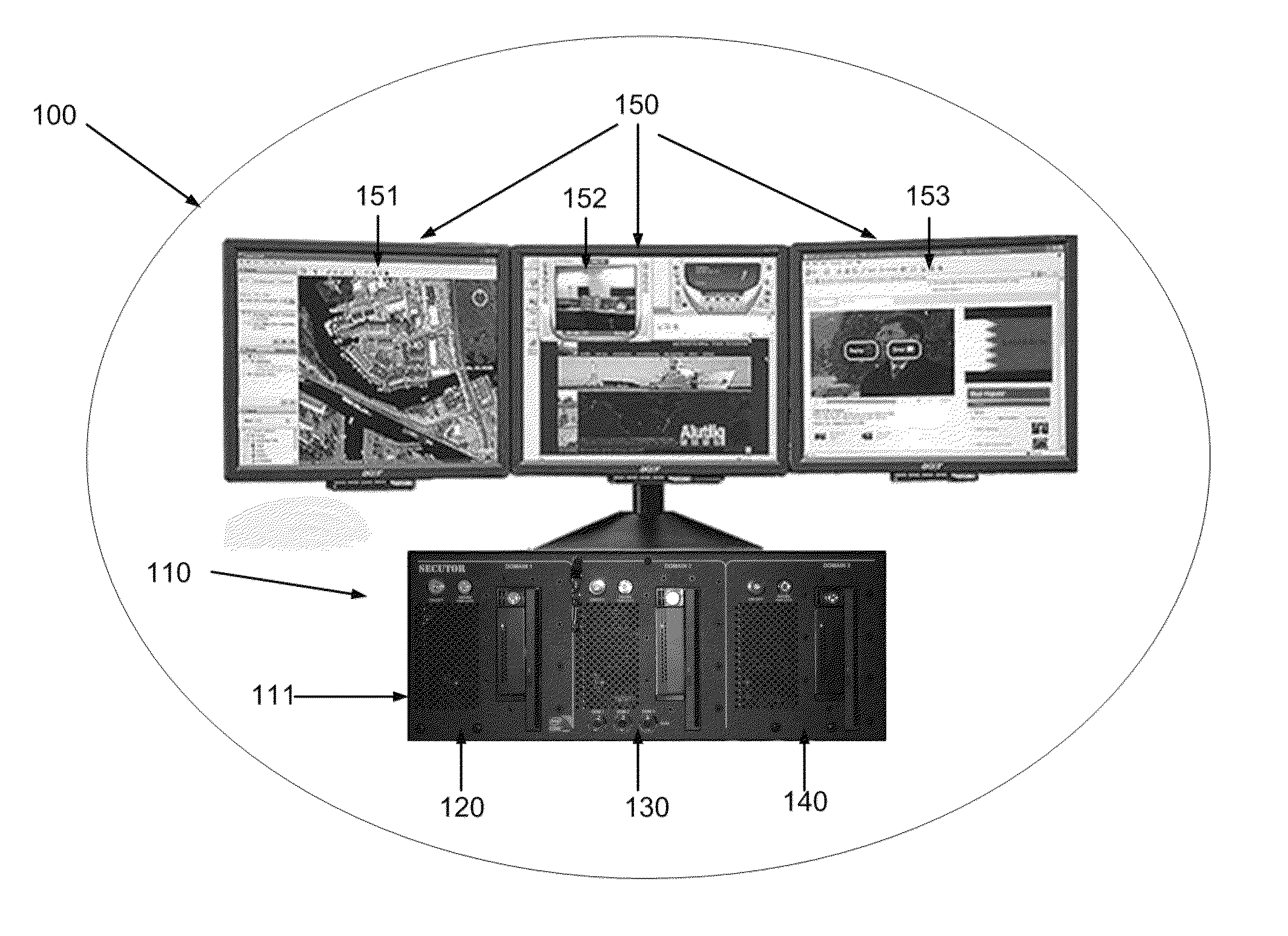
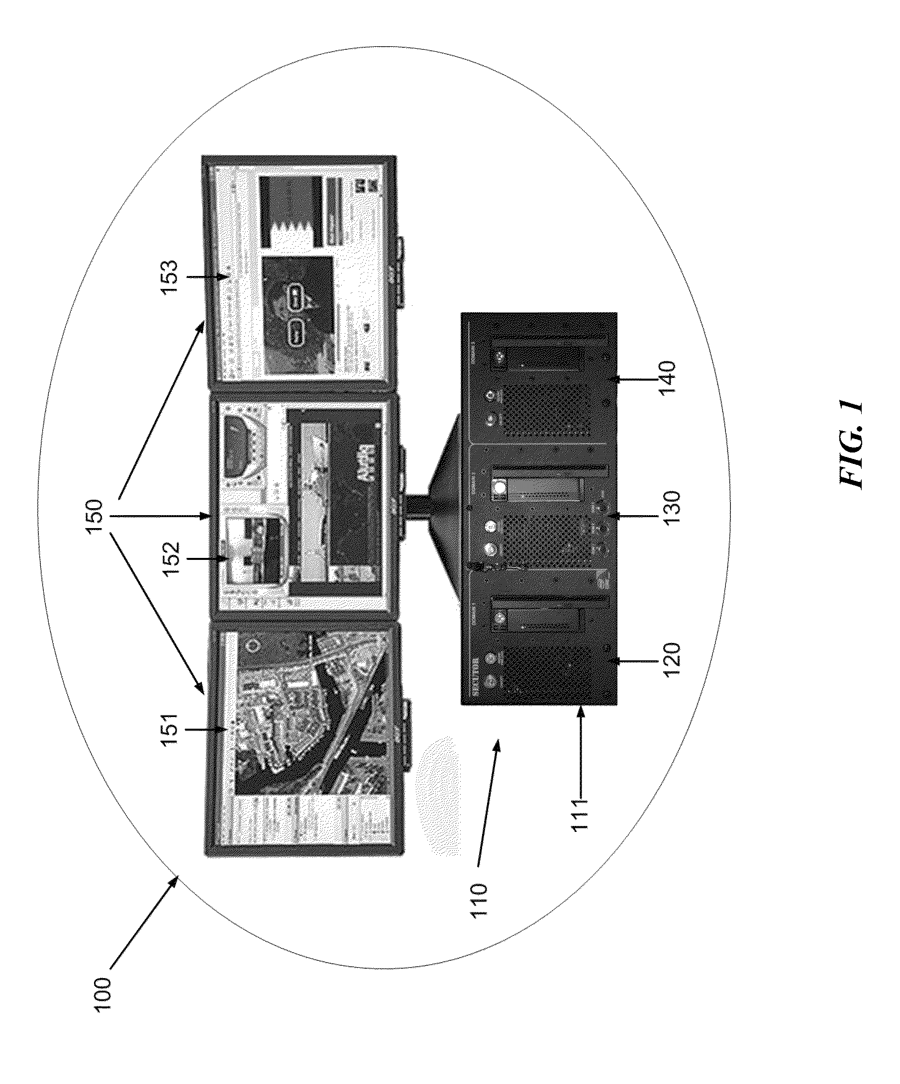
[0062]FIG. 1 illustrates an exemplary embodiment of a multi-level security (MLS) computing system 100, making use of the MLS computer or computing unit 110. The system 100 comprises a multi-level security computer or unit 110 in a single chassis 111, and is generally included with display system 150. Chassis 111 defines a plurality of internal chambers 121, 131, 141 (shown, e.g., in FIG. 5) within which are a plurality of computer domains, shown in this embodiment as computer domains 120, 130, 140. The chassis 111 may be constructed from lightweight, high strength material, which is also highly conductive of electromagnetic energy, such as aluminum.

[0063]As noted above, all chassis components are preferably constructed of principally the same material with common electrical and magnetic conductivity properties, or a coating over the...


PUM


Abstract

Disclosed is a hardware based secure multi-level security computing system system. The system comprises a chassis enclosing multiple separate, secure computer devices or domains, each within an electromagnetic shielding Faraday cage. The chassis structure includes internal electromagnetic shields and other features to prevent cross domain electromagnetic interference or compromising emanations. The chassis may be the size of a standard computer tower. The computer devices or domains may be configured for handling information of different classification levels. Optionally, each of the computer devices may operate on significantly less power than a standard computer. Preferably, each computer operates on no more than 50 Watts of power, more preferably on less than 35 Watts of power.

Description

CROSS-REFERENCE TO RELATED APPLICATION(S)[0001]This application is a continuation-in-part of U.S. application Ser. No. 12 / 182,913, filed Jul. 30, 2008, which claimed the benefit from U.S. Provisional Application Ser. No. 60 / 952,678, filed Jul. 30, 2007, all of which are incorporated herein by reference in their entirety.TECHNICAL FIELD[0002]The present invention relates generally to the field of computer systems, and more particularly, a multi-domain, multi-level security computer system.BACKGROUNDDefinitions[0003]For purposes of convenience without limitation, the following definitions are provided used in this disclosure.[0004](a) Computer: A computer is a programmable machine designed to sequentially and automatically carry out a sequence of arithmetic or logical operations. Conventionally, a computer may include a 1) processor or Computer Processing Unit (CPU) that carries arithmetic and logical operations, 2) data storage device or memory for temporary storage of data for use b...

Claims


Application Information

Patent Timeline
Patent Type & Authority Patents(United States)
IPC IPC(8): G08B13/24H05K7/00G06F21/70G06F21/86G06F1/18H05K5/00
CPCG06F1/181G06F21/86G06F21/87G06F21/53G06F1/182G06F21/81H04K3/825H04K3/68G06F21/70H04K3/20G06F2221/2113G06F2221/2149H04K3/84H04K3/86
Inventor SHIAKALLIS, PETER P.HARVEY, EDMCGINN, JR., JOHNPURSER, GUY
Owner SECUTOR SYST
Why Eureka
Try Eureka