Cooling system for vehicle

a technology for cooling systems and vehicles, applied in the direction of liquid/fluent solid measurements, machines/engines, electric devices, etc., can solve the problem of abnormal driving state of electric pumps, and achieve the effect of improving work efficiency and high precision

Active Publication Date: 2014-02-11
TOYOTA JIDOSHA KK
View PDF12 Cites 23 Cited by
  • Summary
  • Abstract
  • Description
  • Claims
  • Application Information

AI Technical Summary

Benefits of technology

[0014]According to the present invention, abnormalities of the cooling mechanism can be detected with higher precision in such a manner that the abnormalities are distinguished from each other, and therefore, it is a limited part that should be checked when repairs are to be made thereon and the work efficiency is improved.

Problems solved by technology

When the temperature of the coolant in the heater core is lower by a predetermined value or more than the temperature of the coolant in the engine, the control device determines that the drive state of the electric pump is abnormal.

Method used


Image

  • Cooling system for vehicle
  • Cooling system for vehicle
  • Cooling system for vehicle

Examples


Embodiment Construction

[0019]An embodiment of the present invention will hereinafter be described in detail with reference to the drawings. In the drawings, the same or corresponding components are denoted by the same reference characters, and a description thereof will not be repeated.

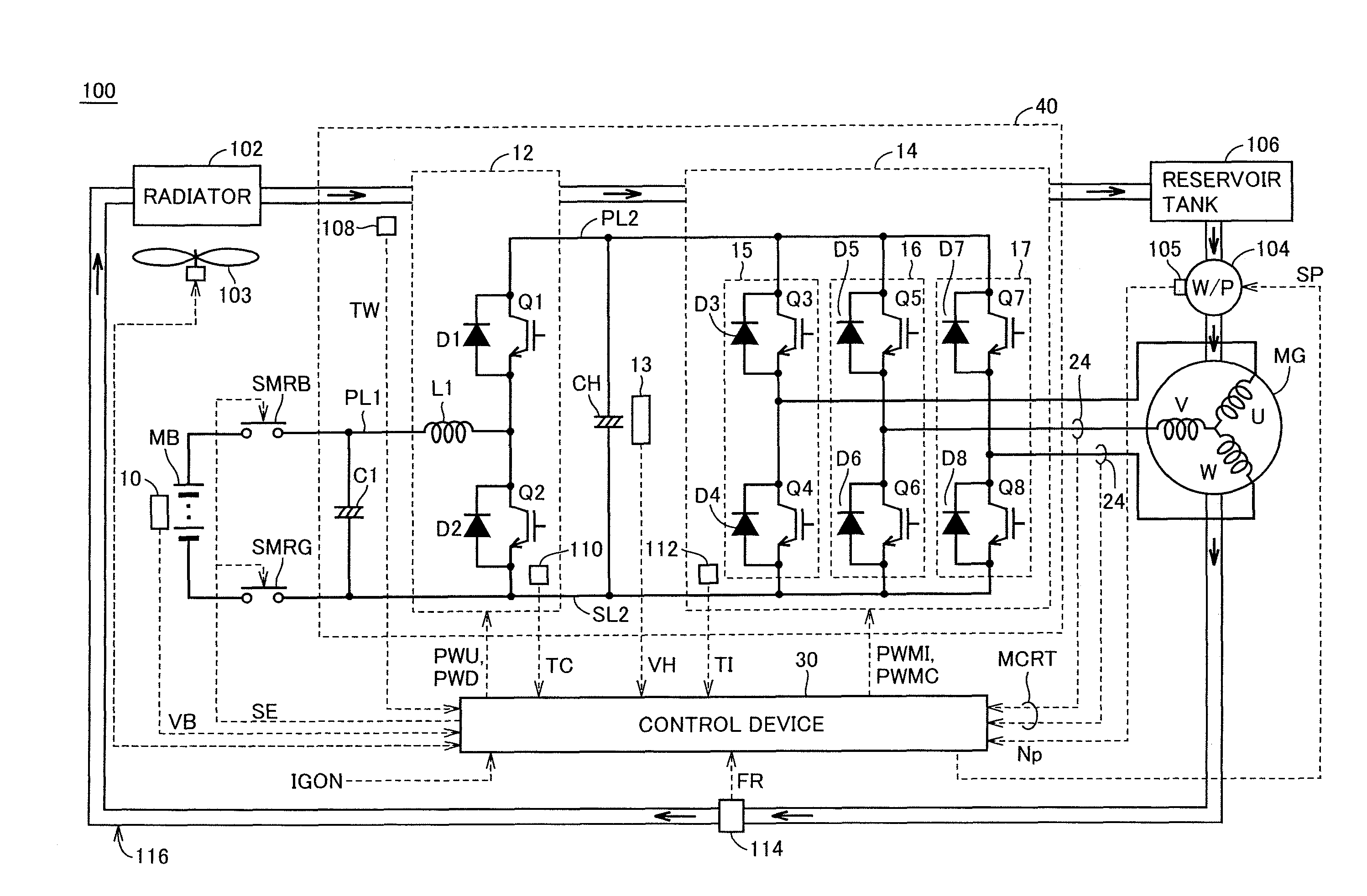
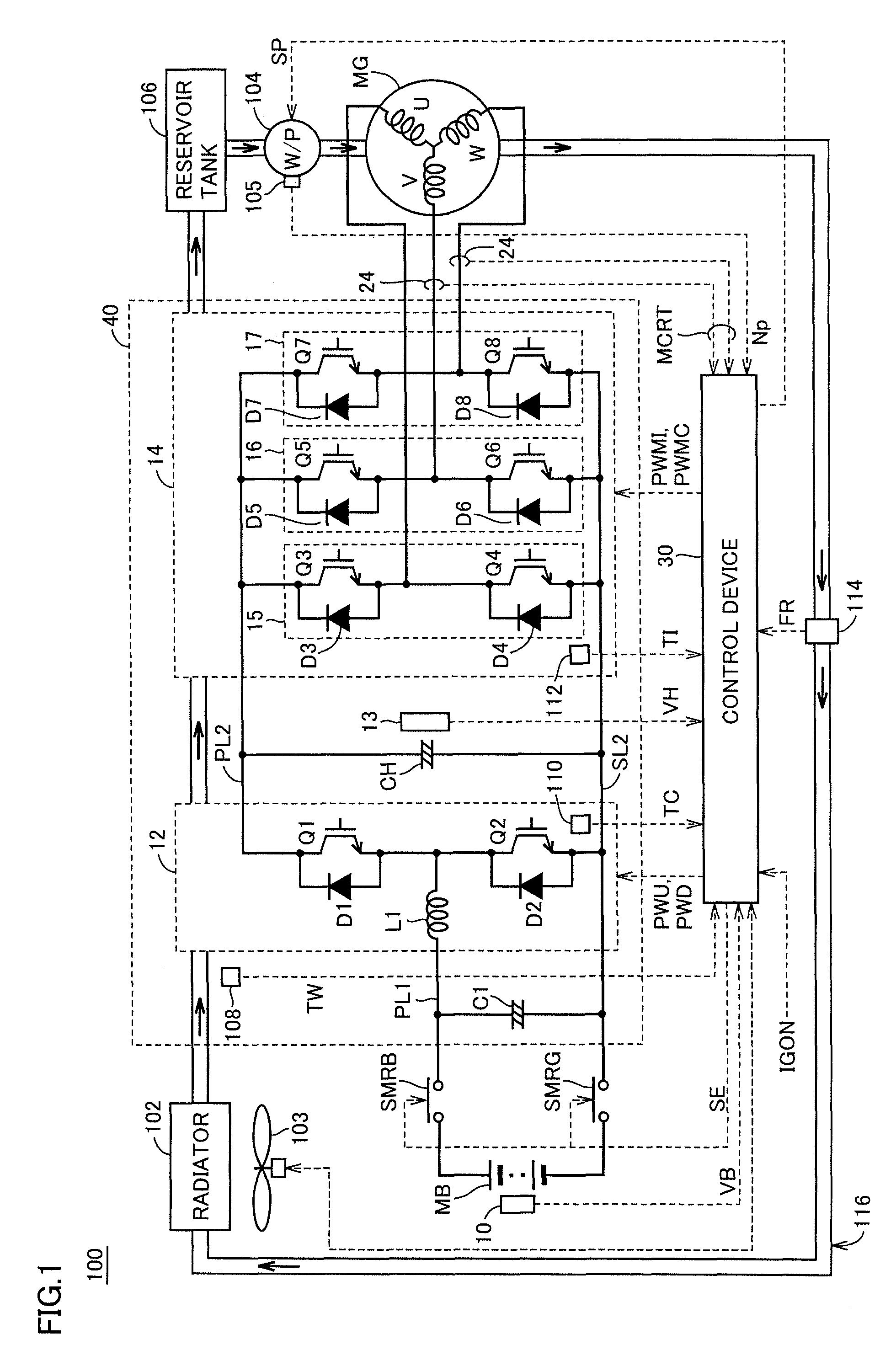
[0020]FIG. 1 is a circuit diagram showing a configuration of a vehicle 100 mounted with a cooling system for the vehicle.

[0021][Description of Drive System]

[0022]Referring to FIG. 1, vehicle 100 includes a battery MB which is a power storage device, a voltage sensor 10, a power control unit (PCU) 40, a motor generator MG, and a control device 30. PCU 40 includes a voltage converter 12, smoothing capacitors C1, CH, a voltage sensor 13, and an inverter 14. Vehicle 100 further includes a positive bus PL2 for feeding electric power to inverter 14 which drives motor generator MG.

[0023]Smoothing capacitor C1 is connected between a positive bus PL1 and a negative bus SL2. Voltage converter 12 boosts a voltage between the terminals...


PUM


Abstract

A vehicle cooling system includes: a channel allowing a liquid medium cooling a drive device of the vehicle to circulate; a flow rate detection unit detecting a flow rate of the liquid medium flowing in the channel; a temperature sensor detecting a temperature of the liquid medium; a pump provided on the channel for circulating the liquid medium; a rotational speed sensor detecting a rotational speed of the pump; and a control device controlling drive of the pump. The control device identifies a malfunctioning part of the cooling system based on the flow rate and the temperature of the liquid medium and the rotational speed of the pump. Thus, since abnormalities of the cooling mechanism can be detected with higher precision so that the abnormalities are distinguished from each other, it is a limited part that should be checked when repairs are made and the work efficiency is improved.

Description

CROSS REFERENCE TO RELATED APPLICATIONS[0001]This application is a National Stage of International Application No. PCT / JP2011 / 055070, filed on Mar. 4, 2011, the contents of all of which are incorporated herein by reference in their entirety.TECHNICAL FIELD[0002]The present invention relates to a cooling system for vehicles, and particularly to a cooling system for vehicles that has a control device identifying a malfunctioning part of the cooling system.BACKGROUND ART[0003]As an example of the technique for making a determination that a failure has occurred to a cooling mechanism of a vehicle, an abnormality determination apparatus is disclosed in Japanese Patent Laying-Open No. 2009-46077 (PTL 1). This abnormality determination apparatus prevents an erroneous determination that the drive state of an electric water pump is abnormal in spite of the fact that the drive state is normal.[0004]Specifically, when the engine is stopped, an electronic control device pressure-feeds a coolant...

Claims


Application Information

Patent Timeline
Patent Type & Authority Patents(United States)
IPC IPC(8): G01M17/00G01F1/34G01F1/86
CPCF01P2031/00F01P2025/06F01P5/14F01P5/10F01P2031/36B60L1/003B60L3/00B60L2240/36B60L58/10Y02T10/70
Inventor NISHIZAWA, JUN
Owner TOYOTA JIDOSHA KK
Why Eureka
Try Eureka