Exhaust emission control device for internal combustion engine

a technology control device, which is applied in mechanical equipment, electric control, machines/engines, etc., can solve the problems of air/fuel ratio feedback control and sub-feedback control that cannot be performed, and achieve the effects of simple control, improved purification rate of exhaust gas purification catalyst, and enhanced control accuracy

Active Publication Date: 2014-02-18
TOYOTA JIDOSHA KK
View PDF7 Cites 2 Cited by
  • Summary
  • Abstract
  • Description
  • Claims
  • Application Information

AI Technical Summary

Benefits of technology

[0044]According to the first invention, a shift in an air / fuel ratio sensor output can be corrected using a lean shift amount of the air / fuel ratio sensor output in accordance with a quantity and / or a proportion of an aldehyde included in an exhaust gas. When alcohol-containing fuel is used, an aldehyde that is an intermediate in an alcohol combustion reaction process is included in an exhaust gas that is discharged from the internal combustion engine, and the aldehyde has an action that shifts the output of the air / fuel ratio sensor to a lean side. According to the first invention, since a shift in an output of the air / fuel ratio sensor that is caused by an aldehyde can be appropriately corrected, precise feedback control can be performed with respect to the air / fuel ratio. Thus, the purification rate of the exhaust gas purification catalyst can be improved.
[0045]According to the second invention, a shift in the output of the air / fuel ratio sensor caused by an aldehyde can be appropriately corrected by means of a simple configuration.
[0046]According to the third invention, an aldehyde concentration or a ratio between an aldehyde concentration and a hydrogen concentration in an exhaust gas that is discharged from an internal combustion engine can be exactly estimated by a simple method.
[0047]According to the fourth invention, by performing exhaust gas component ratio control, a ratio between an aldehyde concentration and a hydrogen concentration in an exhaust gas that is discharged from an internal combustion engine can be controlled so as to be close to a target ratio. An aldehyde has an action that shifts an air / fuel ratio sensor output to a lean side and hydrogen has an action that shifts an air / fuel ratio sensor output to a rich side, and a shift in the air / fuel ratio sensor output is determined by a balance (ratio) between the aldehyde and the hydrogen. A ratio between an aldehyde concentration and a hydrogen concentration in an exhaust gas discharged from an internal combustion engine at a predetermined timing after engine start-up normally differs depending on the engine temperature when the engine is started. In this respect, according to the fourth invention, by performing exhaust gas component ratio control, irrespective of the engine temperature at the time of engine start-up, the ratio between an aldehyde concentration and a hydrogen concentration can be controlled so as to be close to a predetermined target ratio. Consequently, irrespective of the engine temperature at the time of engine start-up, a shift in an air / fuel ratio sensor output can be appropriately corrected using the same output shift correction value. Thus, the control is simple, and the control accuracy can also be enhanced.
[0048]According to the fifth invention, exhaust gas component ratio control can be performed in association with a timing at which feedback control of the air / fuel ratio starts or at a timing at which an exhaust gas purification catalyst is activated. Consequently, exhaust gas component ratio control can be executed at an appropriate timing.
[0049]According to the sixth invention, an appropriate output shift correction value can be set in accordance with an alcohol concentration of a fuel. Therefore, even when fuels with various alcohol concentrations are used, a shift in an air / fuel ratio sensor output can be corrected with greater accuracy.

Problems solved by technology

However, at a time of engine start-up, since the air / fuel ratio sensor and the sub-exhaust gas sensor are not activated, air / fuel ratio feedback control and sub-feedback control can not be performed until the air / fuel ratio sensor and the sub-exhaust gas sensor are warmed up and activated.

Method used


Image

  • Exhaust emission control device for internal combustion engine
  • Exhaust emission control device for internal combustion engine
  • Exhaust emission control device for internal combustion engine

Examples


embodiment 1

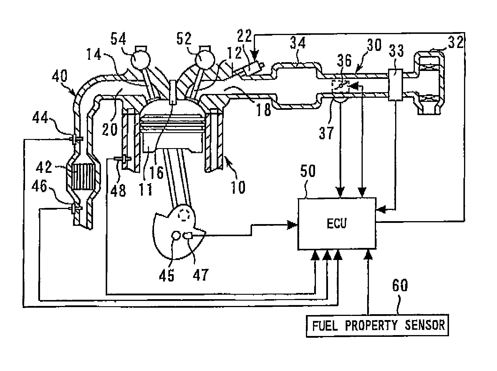
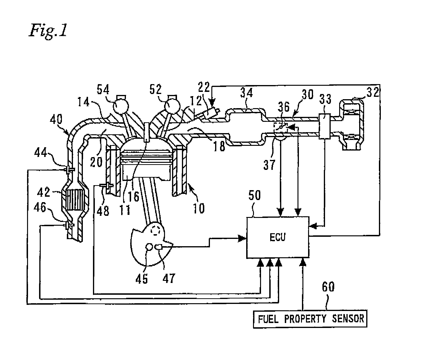
[0064]FIG. 1 is a view for describing a system configuration of Embodiment 1 of the present embodiment. As shown in FIG. 1, a system according to the present embodiment includes an internal combustion engine 10. The internal combustion engine 10 of the present invention can operate using gasoline as a fuel, and can also operate using a fuel in which an alcohol such as ethanol or methanol and gasoline are mixed (hereunder, also referred to as “alcohol-containing fuel”). In this case, a fuel in which a concentration of an alcohol component (proportion of an alcohol component) is from a low concentration (for example, about several %) to a high concentration (for example, 80% or more) can be used as an alcohol-containing fuel.

[0065]Each cylinder of the internal combustion engine 10 includes a piston 11, an intake valve 12, an exhaust valve 14, a spark plug 16, an intake port 18 and an exhaust port 20 that communicate inside the cylinder, and a fuel injector 22 that injects a fuel into ...


PUM


Abstract

An exhaust emission control apparatus for an internal combustion engine includes: an exhaust gas purification catalyst arranged in an exhaust gas passage of the internal combustion engine; an air / fuel ratio sensor installed on an upstream side of the exhaust gas purification catalyst and detects an air / fuel ratio of an exhaust gas discharged from the internal combustion engine; air / fuel ratio feedback control means that performs feedback control of the air / fuel ratio based on an output of the air / fuel ratio sensor; and sensor output correcting means that corrects a shift in the output of the air / fuel ratio sensor. The sensor output correcting means is configured so as to correct a shift in the output of the air / fuel ratio sensor using a lean shift amount of the air / fuel ratio sensor output in accordance with a quantity and / or a proportion of an aldehyde included in the exhaust gas.

Description

TECHNICAL FIELD[0001]The present invention relates to an exhaust emission control apparatus for an internal combustion engine.BACKGROUND ART[0002]In order to obtain a high purification rate with an exhaust gas purification catalyst (three-way catalyst) of an internal combustion engine, it is necessary for the air / fuel ratio of the exhaust gas to be in the vicinity (purification window) of a stoichiometric air / fuel ratio. Therefore, the air / fuel ratio of the exhaust gas is detected by an air / fuel ratio sensor that is installed on an upstream side of the exhaust gas purification catalyst, and air / fuel ratio feedback control is performed that corrects a fuel injection quantity so that the air / fuel ratio becomes the stoichiometric air / fuel ratio.[0003]A technique is also being widely used in which a sub-exhaust gas sensor that is constituted by an oxygen sensor or the like is further provided on a downstream side of an exhaust gas purification catalyst, and sub-feedback control for supp...

Claims


Application Information

Patent Timeline
Patent Type & Authority Patents(United States)
IPC IPC(8): F02B13/00F01N3/00F01N3/10
CPCF02D2041/001F01N11/00F02D41/1487F02D19/084Y02T10/36F02D41/1444F02D41/064F02D41/1488F02D41/1441F02D41/1456F02D19/087F02D2200/0611Y02T10/30
Inventor TSUKAGOSHI, TAKAHIROMORITA, KOUJI
Owner TOYOTA JIDOSHA KK
Why Eureka
Try Eureka