
Automatic seepage meter

a seepage meter and automatic technology, applied in the direction of liquid/fluent solid measurement, machines/engines, instruments, etc., can solve the problem of difficult to obtain information on the temporal evolution of seepag

Inactive Publication Date: 2014-02-18
KOREA INST OF GEOSCI & MINERAL RESOURCES
View PDF17 Cites 10 Cited by
  • Summary
  • Abstract
  • Description
  • Claims
  • Application Information

AI Technical Summary

Benefits of technology

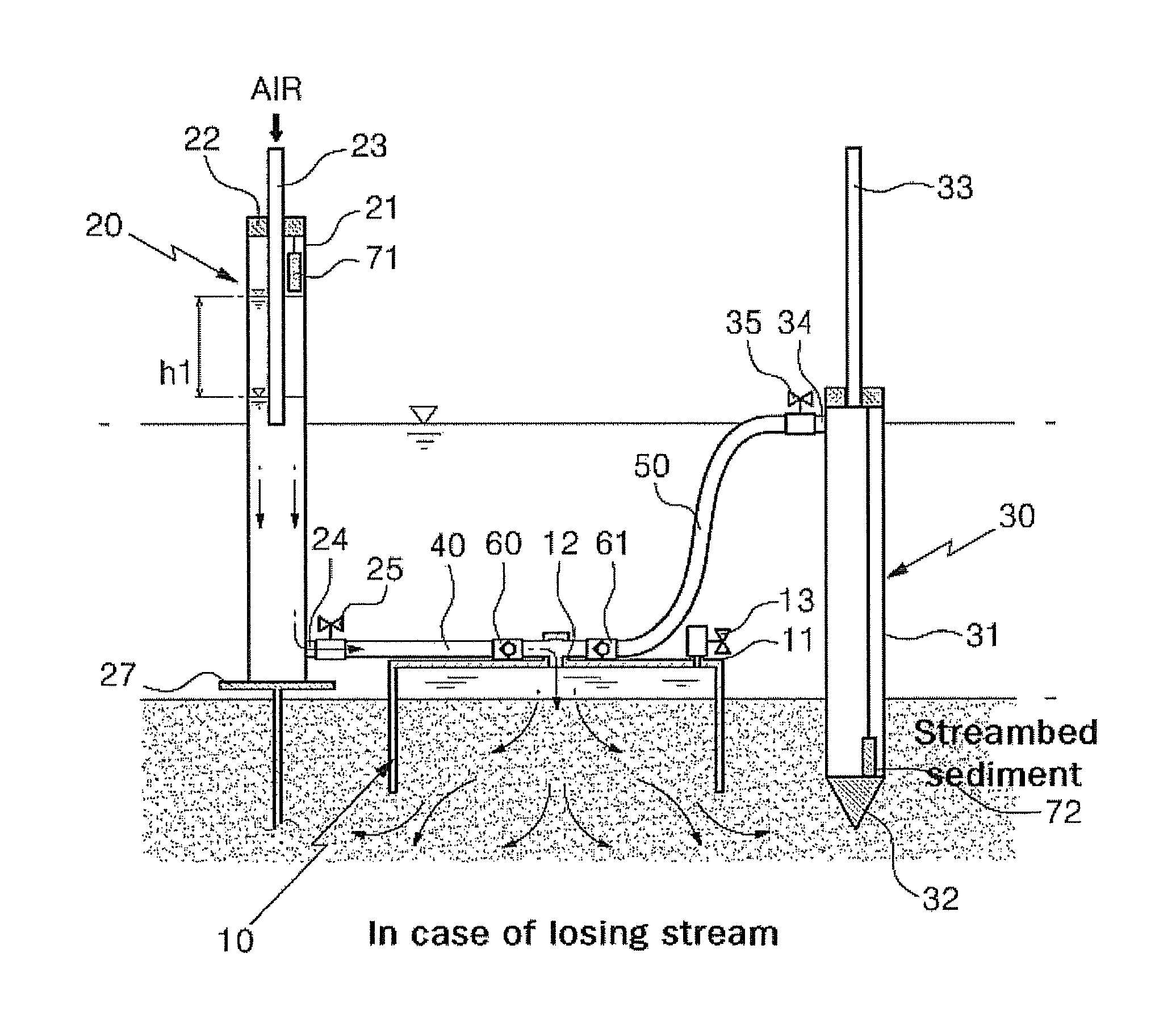
The present invention solves the problem of measuring changes in seepage flux in a mixed zone of stream by inducing changes in discharge and recharge amounts of groundwater through the use of a Mariotte siphon. The invention utilizes two check valves to induce changes in discharge and recharge amounts of groundwater separately to changes in water levels in two cylindrical water baths. The invention also utilizes the hydraulic pressure by water depth from a top end of a chamber to a water surface of stream and the pressure by atmospheric pressure in the chamber to prevent water flow from the water bath to the chamber. The invention further provides a water bath for measuring groundwater recharge by applying the Mariotte siphon principle to flow water of the water bath for measuring recharge in case of losing stream where groundwater level is lower than surface water level.

Problems solved by technology

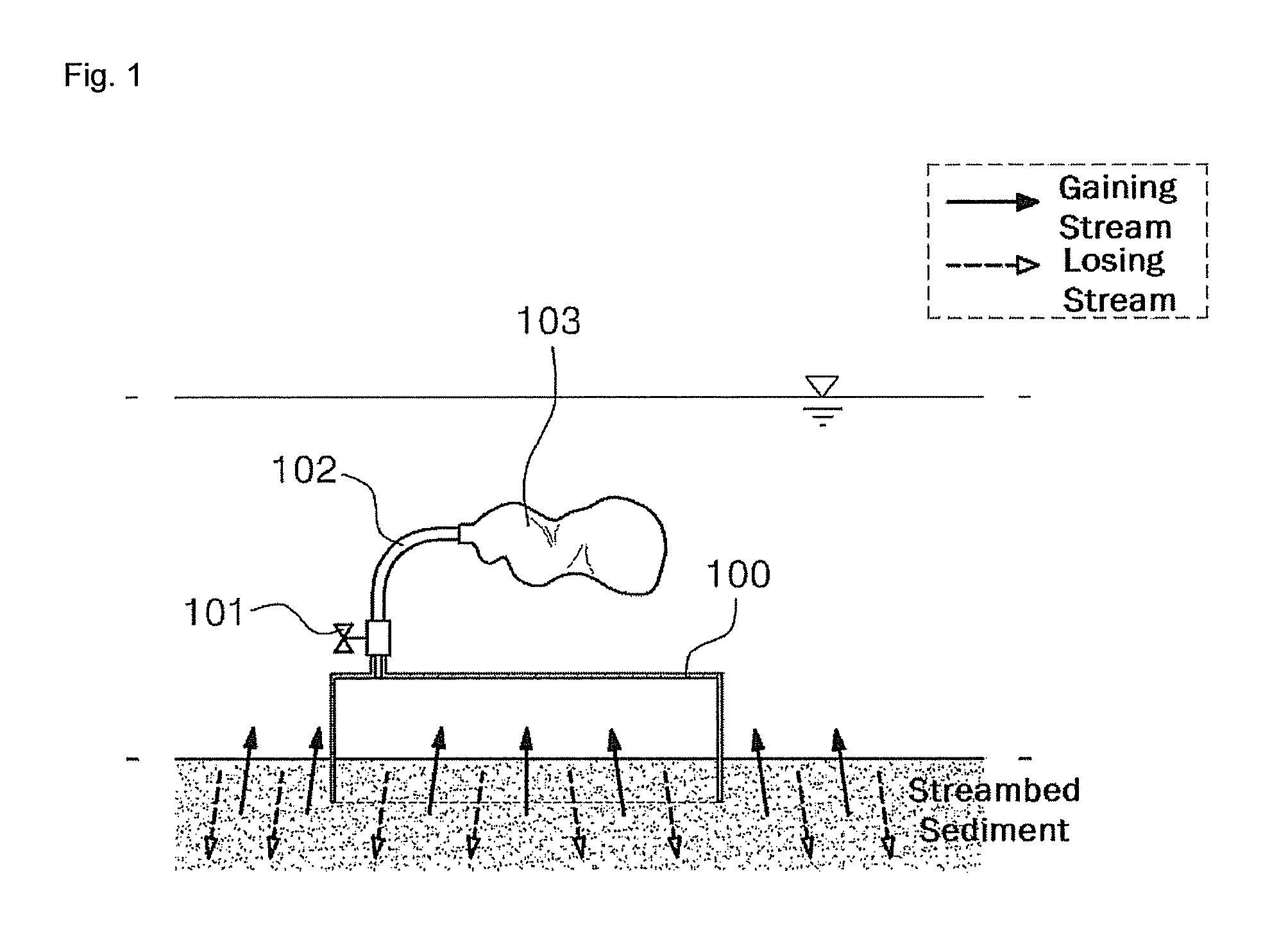
Since the seepage meter proposed by Lee (1977) is a manual measuring type that directly measures an amount of water increased or decreased in the collection bag 103 after elapsing a certain time, it is difficult to obtain information on the temporal evolution of seepage.

Method used


Image

  • Automatic seepage meter
  • Automatic seepage meter
  • Automatic seepage meter

Examples


Embodiment Construction

[0023]Before describing detailed description of various exemplary embodiments of the present invention, it will be understood that detail construction and arrangements of the constituting elements described in the following description and illustrated drawings shall not restrict their application. The present invention can be realized and embodied by other exemplary embodiments, and can be performed by various methods. It will be further understood that expression and words in the present invention regarding the terms related to directions of devices and elements (for example “front”, “back”, “up”, “down, “top”, “bottom”, “left”, “right”, “lateral”, etc) are used only to simplify a description of the present invention but are not represented nor meant for the related devices and the elements to be directed simply along a particular direction.

[0024]The present invention has following features to accomplish the said object.

[0025]The present invention will now be described more fully h...


PUM


Abstract

The present invention relates to an automatic seepage meter for measuring groundwater-surface water exchange in a mixed zone of stream. The present invention includes: the chamber installed in streambed sediment; the device for measuring amount of groundwater recharge through a change in water level accompanied by discharging water in the water in case of losing stream; and the device for measuring amount of groundwater discharge through a change in water level according to an increased water from the chamber to the water bath for measuring discharge in case of gaining stream.

Description

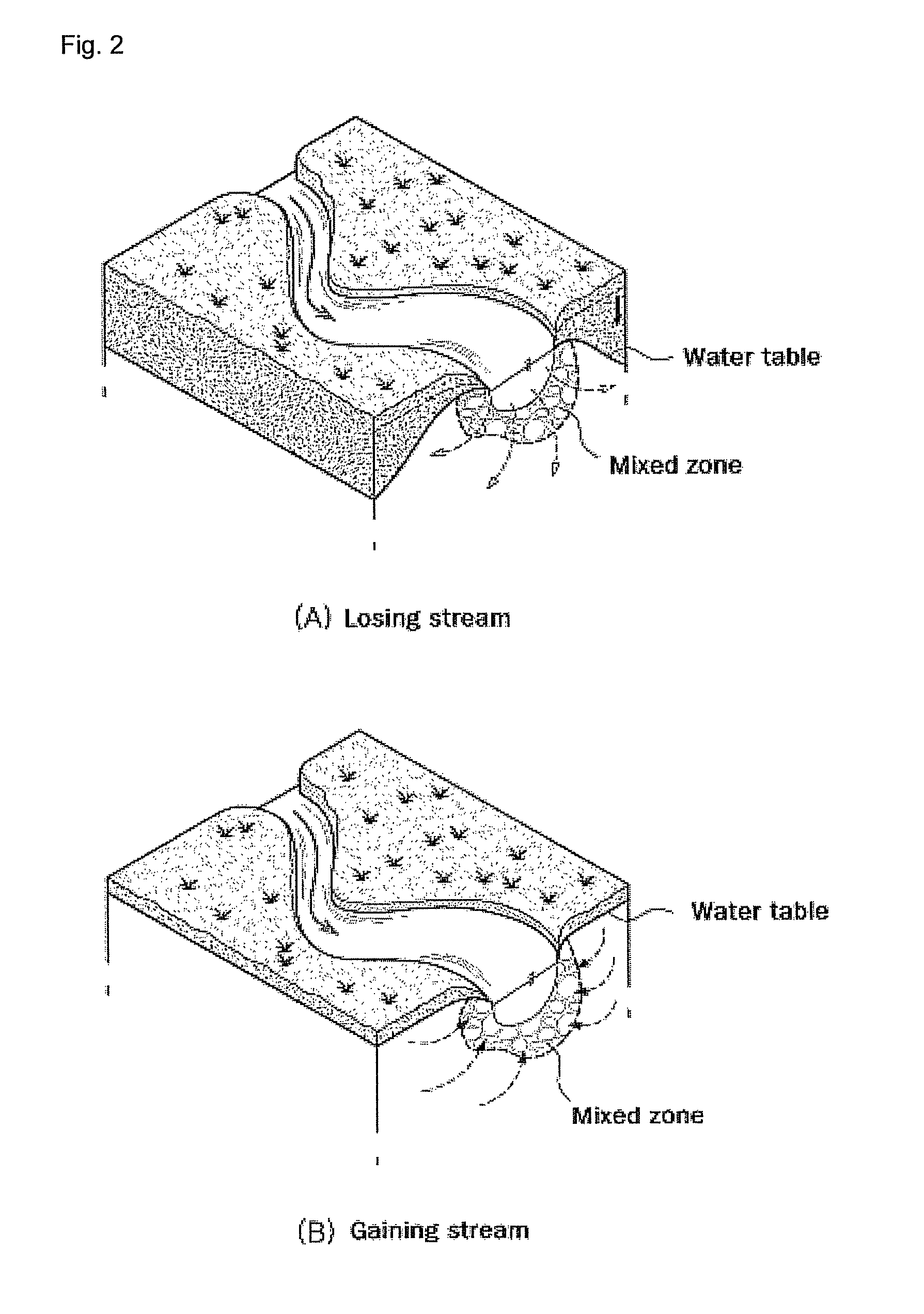
CROSS-REFERENCE TO RELATED PATENT APPLICATION[0001]This application claims the benefit of and priority to Korean Patent Application No. 10-2011-0069086, filed on Jul. 12, 2011, in the Korean Intellectual Property Office, the disclosure of which is incorporated herein in its entirety by reference.BACKGROUND OF THE INVENTION[0002]1. Field of the Invention[0003]The present invention relates to an automatic seepage meter for measuring groundwater-surface water exchange in a mixed zone of stream.[0004]2. Description of the Related Art[0005]Seepage meters are instruments for measuring the flow of water between groundwater and a surface water body such as a lake, wetland, estuary, or stream. Such seepage meters were used in the 1940s and 1950s to measure water loss in irrigation canals (Israelson and Reeve, 1944; Warnick, 1951; Robinson and Rhower, 1952), and Lee (1977) devised and used a seepage meter of half-barrel shape to evaluate an interaction between groundwater and surface water.[0...

Claims


Application Information

Patent Timeline
Patent Type & Authority Patents(United States)
IPC IPC(8): G01F1/34G01F1/37
CPCG01F23/14G01F1/00G01F22/00G01F23/00
Inventor LEE, BONG JOOKO, KYUNG SEOK
Owner KOREA INST OF GEOSCI & MINERAL RESOURCES
Learn More