Supercharge Your Innovation With Domain-Expert AI Agents!

Audio signal processing apparatus

a technology of audio signal and processing apparatus, which is applied in the field of audio signal processing apparatus, can solve the problems of limited flexibility associated with switching noise processes, unwanted recording of audio signals, etc., and achieve the effects of reducing driving noise, reducing driving noise, and reducing driving nois

Inactive Publication Date: 2014-02-18
CANON KK
View PDF29 Cites 2 Cited by
  • Summary
  • Abstract
  • Description
  • Claims
  • Application Information

AI Technical Summary

Benefits of technology

The present invention provides an audio signal processing apparatus that reduces driving noise of a removable lens unit. The apparatus includes a connection unit that connects with the lens unit, a microphone unit that acquires audio signals, an audio processor that processes the audio signals to reduce the driving noise, and a controller that detects the type of lens unit and controls the audio processor to perform the appropriate reduction process. The first reduction process uses a signal generated based on an audio signal of previous or subsequent to a noise section of the driving noise, while the second reduction process attenuates a part of the driving noise. This results in a cleaner audio signal with less noise, improving the overall quality of the audio signal.

Problems solved by technology

Driving noise generated at that time is mixed in an audio signal, and an audio signal which is not required by the user may be unwantedly recorded.
Therefore, flexibility associated with switching of the noise processes is limited.

Method used


Image

  • Audio signal processing apparatus
  • Audio signal processing apparatus
  • Audio signal processing apparatus

Examples


first embodiment

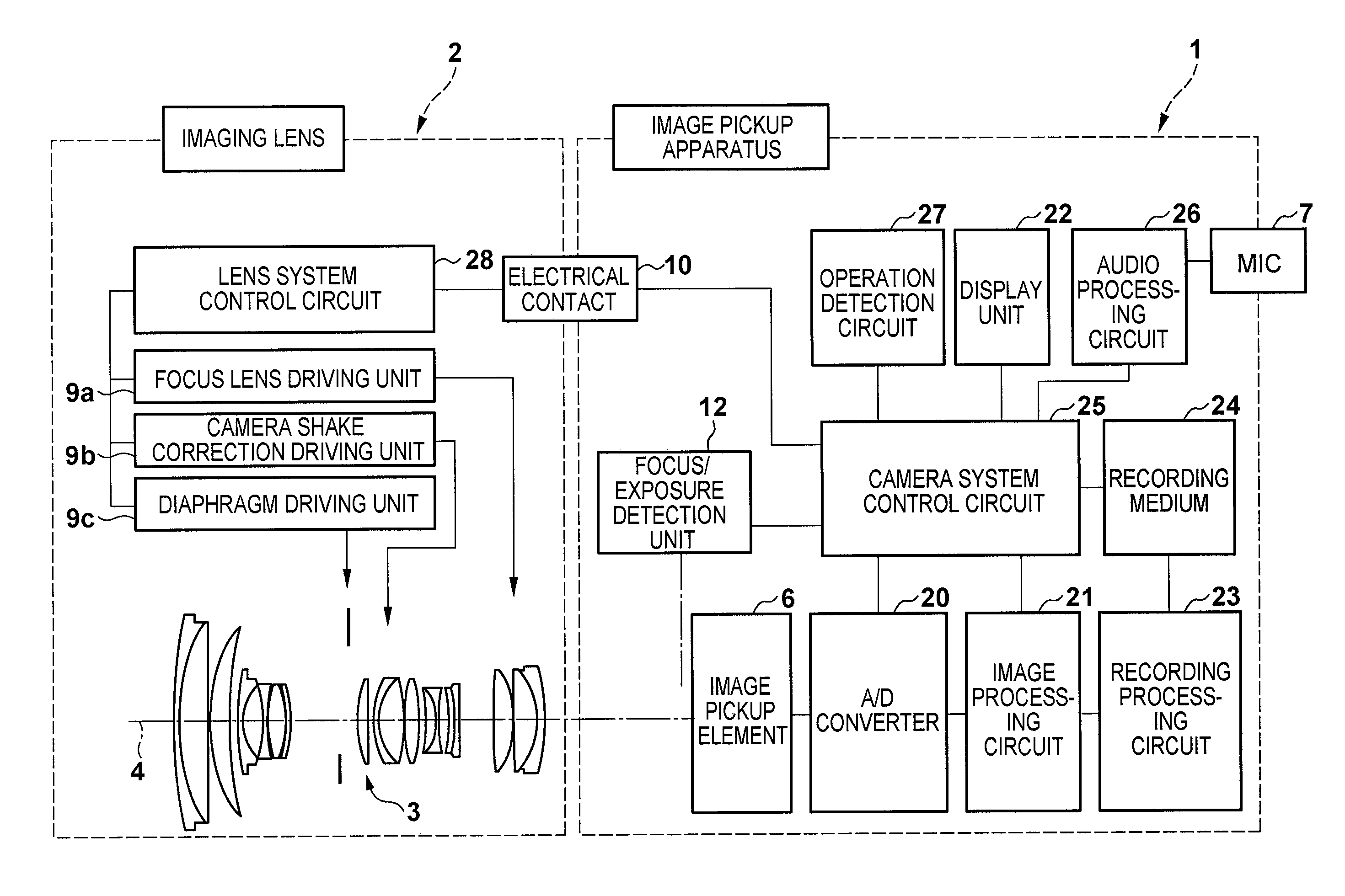
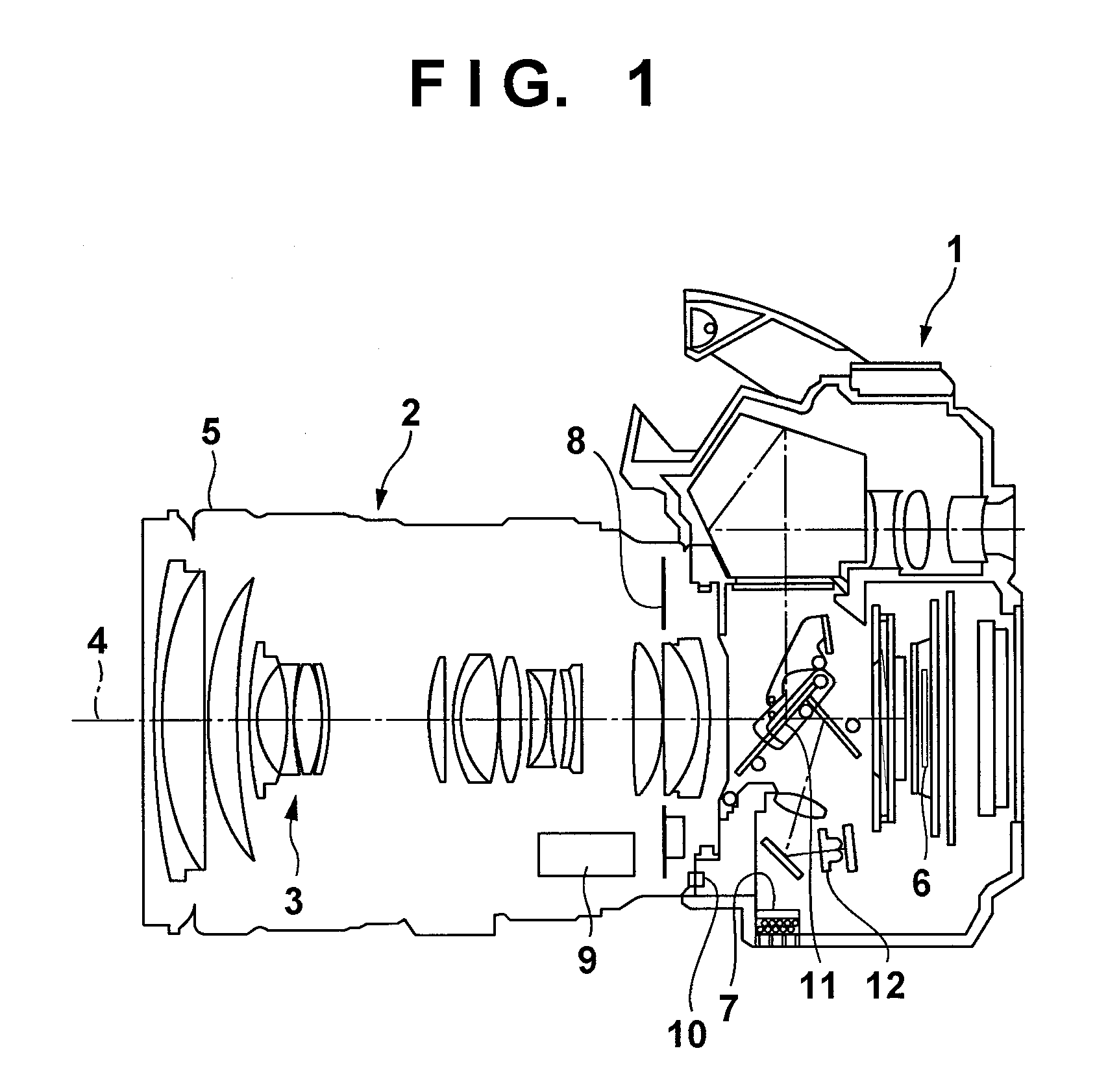
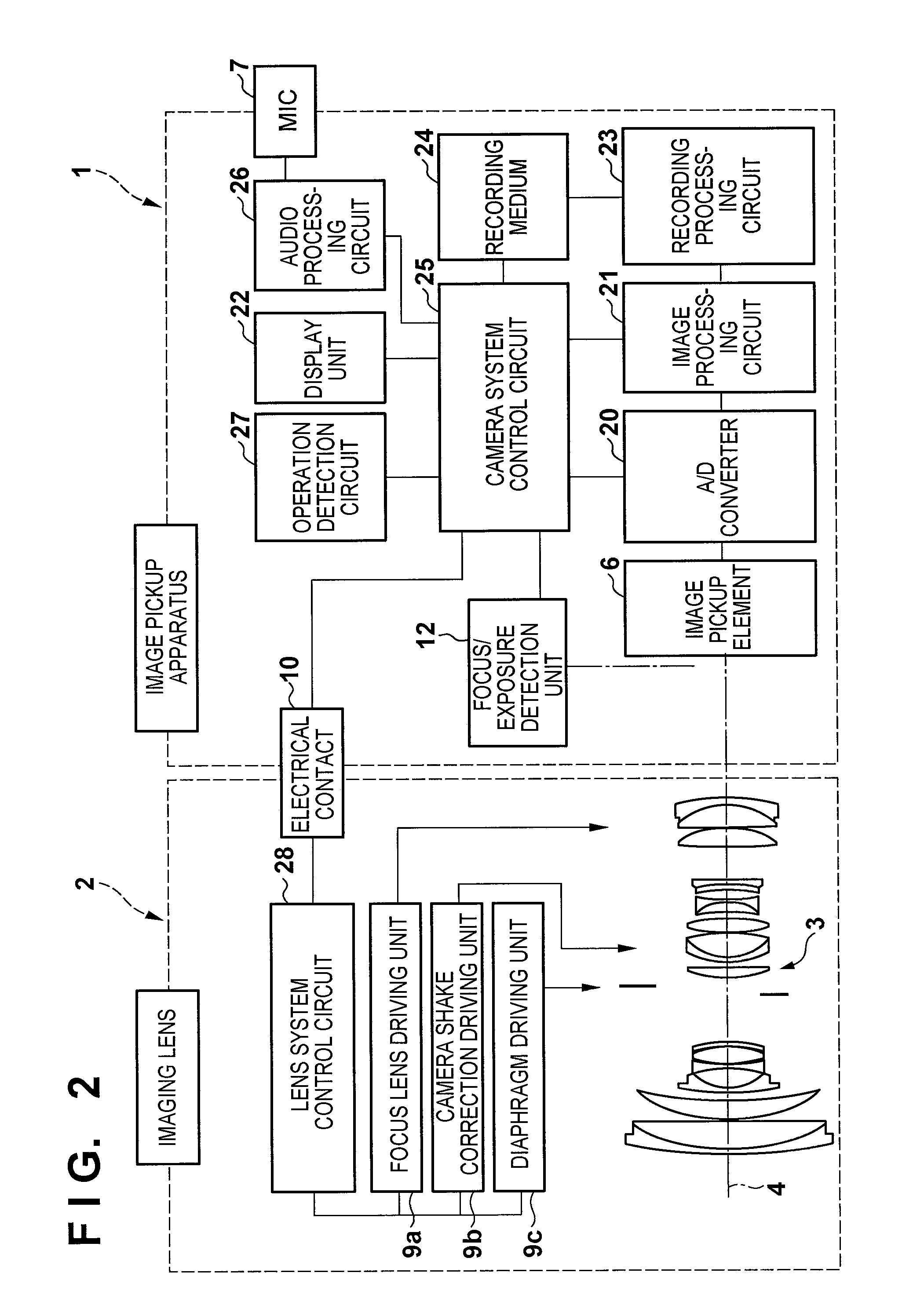
[0025]FIG. 1 is a sectional view of an image pickup apparatus 1 according to the first embodiment, and an imaging lens 2 connected to it. Note that the imaging lens 2 may be either detachable from the image pickup apparatus 1 or integrated with the image pickup apparatus 1. In FIG. 1, reference numeral 3 denotes an photographing optical system; 4, an optical axis of the imaging lens 2; 5, a lens barrel; 6, an image pickup element; 7, a microphone provided to the image pickup apparatus 1; 8, a board required to execute lens control; and 9, an optical system driving unit required to adjust the photographing optical system 3. Reference numeral 10 denotes contacts used to connect the image pickup apparatus 1 and imaging lens 2; 11, a so-called quick return mirror; and 12, a focus / exposure detection unit which includes AE / AF sensors.

[0026]The image pickup apparatus 1 adjusts the photographing optical system 3 by executing focus / exposure detection using the imaging lens 2 and focus / exposu...

second embodiment

[0074]The second embodiment will explain in detail a case in which filter processing is selected depending on a type of a component which generates noise even when an operation period is short. The second embodiment adopts the same arrangement of the image pickup apparatus 1 and the like as those of the first embodiment, unless otherwise specified.

[0075]FIGS. 10A and 10B are flowcharts showing the sequence of selection of noise processing methods according to the second embodiment. In FIGS. 10A and 10B, the same step numbers denote steps in which the same processes as in FIG. 3 are executed, and a description thereof will not be repeated.

[0076]Upon reception of a moving image pickup / audio recording start instruction via an operation button (not shown), the camera system control circuit 25 starts a moving image pickup operation in step S201.

[0077]In step S203, the camera system control circuit 25 measures a luminance level by applying appropriate signal processing to luminance signal...


PUM


Abstract

The controller controls the audio processor to perform the first reduction process, in a case where the type of the connected removable lens unit is a first type lens unit, the controller controls the audio processor to perform the second reduction process, in a case where the type of the connected removable lens unit is a second type lens unit.

Description

BACKGROUND OF THE INVENTION[0001]1. Field of the Invention[0002]The present invention relates to an audio signal processing apparatus.[0003]2. Description of the Related Art[0004]Conventionally, as an audio signal processing apparatus, image pickup apparatuses such as cameras, which can pick up moving images, are known. Each of these image pickup apparatuses drives driven units such as, for example, a lens, diaphragm, and the like, which units are incorporated in itself, so as to pick up a moving image. Driving noise generated at that time is mixed in an audio signal, and an audio signal which is not required by the user may be unwantedly recorded. To solve this problem, various proposals have been conventionally made.[0005]In Japanese Patent Laid-Open No. 2006-203376, a digital camera switches noise processing methods according to an operation time period of a motor used to adjust an optical system. Thus, noise processing is executed according to the motor operation time period, th...

Claims


Application Information

Patent Timeline
Patent Type & Authority Patents(United States)
IPC IPC(8): H04B15/00H04N5/76G03B17/24G10L19/005G10L21/0208
CPCH04N9/8063H04N5/772G10L21/0208H04R3/00H04N23/00
Inventor KIMURA, MASAFUMI
Owner CANON KK
Features
  • R&D
  • Intellectual Property
  • Life Sciences
  • Materials
  • Tech Scout
  • Unparalleled Data Quality
  • Higher Quality Content
  • 60% Fewer Hallucinations
Learn More