
Liquid sample heating vaporizer

a liquid sample and heating technology, applied in the direction of thermometer details, chemical/physical processes, machines/engines, etc., can solve the problems of sample thermal decomposition, difficult to perform temperature control with high accuracy, poor response property of liquid sample temperature control, etc., to achieve the effect of improving the response property and accuracy of temperature control of liquid sampl

Active Publication Date: 2014-03-04
HORIBA STEC CO LTD
View PDF11 Cites 6 Cited by
  • Summary
  • Abstract
  • Description
  • Claims
  • Application Information

AI Technical Summary

Benefits of technology

This patent improves the ability to control the temperature of a liquid sample to a higher level of accuracy and response.

Problems solved by technology

As a result, there exists a problem that the response property of the temperature control of the liquid sample is poor.
Also, even in the case of performing the temperature control with use of the temperature detection values of the liquid temperature sensor and the heater temperature sensor, the temperature on the inside surface of the bottom wall or the like serving as a heating surface is unknown, and therefore it is difficult to perform the temperature control with high accuracy.
In particular, in the case where a temperature enabling a required vapor pressure to be ensured, and a temperature (decomposition point) causing it to be thermally decomposed are close to each other, in the configuration in which the response property of the temperature control is poor, and highly accurate temperature control cannot be performed as described above, the liquid sample is thermally decomposed, and a problem becomes significant.
In addition, in order to solve a problem of a temperature reduction near a liquid surface, which is one of problems inherent in temperature control of a liquid sample, Patent literature 1 describes a vaporizing tank in which a cartridge heater is arranged near a liquid surface.
If so, as described above, the control response property is poor, and controlling to a set temperature with high accuracy is also difficult.

Method used


Image

  • Liquid sample heating vaporizer
  • Liquid sample heating vaporizer
  • Liquid sample heating vaporizer

Examples


Embodiment Construction

[0020]One embodiment of a sample gas supply system using a liquid sample heating vaporizer according to the present invention will hereinafter be described with reference to the drawings.

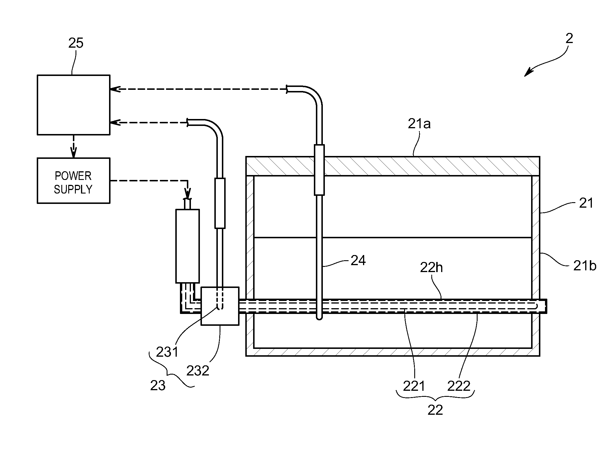
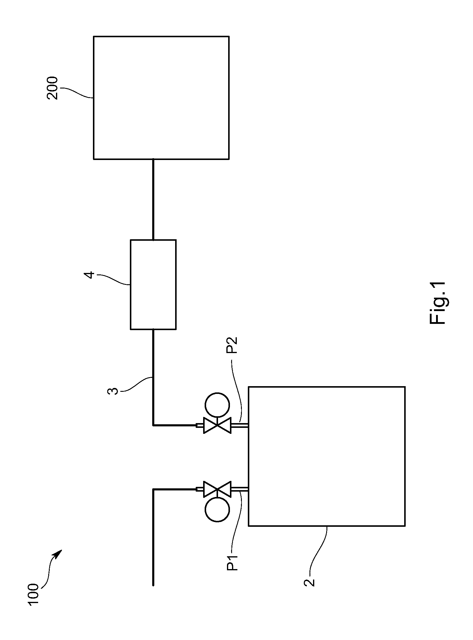
[0021]A sample gas supply system 100 according to the present embodiment is one that is incorporated in, for example, a semiconductor manufacturing system or a solar cell manufacturing system, and as illustrated in FIG. 1, is provided with a liquid sample heating vaporizer 2 that heats and vaporizes a liquid sample, a supply line 3 that is connected to an outlet port P2 of the liquid sample heating vaporizer 2 to supply a vaporized liquid sample (hereinafter referred to as sample gas) to a target device 200 such as a chamber, and a flow rate control device 4 that is provided in the supply line 3 and controls a flow rate of the sample gas, such as a mass flow controller (MFC). In the present embodiment, as the liquid sample, a sample of which a temperature enabling a required vapor pressure to be ens...


PUM

PropertyMeasurementUnit
temperatureaaaaaaaaaa
surface temperatureaaaaaaaaaa

Abstract

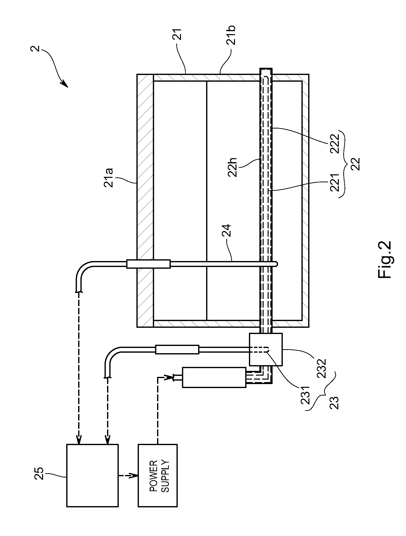
The present invention is intended to improve response property and accuracy of temperature control of a liquid sample, and is provided with a vaporization tank that retains the liquid sample, one or more heaters that are provided in the vaporization tank and respectively have heating parts that come into contact with the liquid sample to heat the liquid sample, a temperature detection part that is provided in contact with an outer surface including the heating part of any of the heaters and detects a temperature of the outer surface, and a control part that receives a temperature detection signal from the temperature detection part to control electric power supplied to the heaters.

Description

TECHNICAL FIELD[0001]The present invention relates to a liquid sample heating vaporizer for heating and vaporizing a liquid sample retained in a vaporization tank.BACKGROUND ART[0002]A conventional liquid sample heating vaporizer is, as illustrated in FIG. 6, provided with a vaporization tank having an inlet port for introducing a liquid sample and an outlet port for leading out a vaporized liquid sample, and heaters for heating and vaporizing the liquid sample retained in the vaporization tank. The heaters are provided outside a bottom wall and side walls, and configured to heat the liquid sample through the bottom and side walls. Temperature control of the liquid sample at the time of heating is performed by using temperature detection values from a liquid temperature sensor that detects a temperature of the liquid sample, and a heater temperature sensor provided for the heaters.[0003]However, in the above configuration, surfaces that heat the liquid sample are an inside surface o...

Claims


Application Information

Patent Timeline
Patent Type & Authority Patents(United States)
IPC IPC(8): G01N1/44B01F3/04
CPCH01L21/67109G01K1/18B01B1/06B01D1/0017B01D1/0082B01D1/30G01N1/44B01J7/02B01D1/00
Inventor OBA, HIDENORINAGANO, TADAYUKI
Owner HORIBA STEC CO LTD
Learn More