Eureka AIR delivers breakthrough ideas for toughest innovation challenges, trusted by R&D personnel around the world.

Pivoting display device used in aircraft

a display device and aircraft technology, applied in the field of aircraft display devices, can solve the problems of complicated mechanism, high load on the motor used for this, and easy problems such as the operation reliability of the motor when driven by the motor, so as to reduce the load, improve the reliability of the operation, and efficiently charge and discharge capacitors.

Active Publication Date: 2014-03-04
AIRCRAFT CABIN SYST
View PDF8 Cites 12 Cited by
  • Summary
  • Abstract
  • Description
  • Claims
  • Application Information

AI Technical Summary

Benefits of technology

[0009]The aim of the present invention is to meet the requirement of the Federal Aviation Administration (FAA) and to provide a pivoting display device for aircraft that is capable of securely driving the monitor to the stowage position in case of a power failure. Further aims of embodiments of the invention are to effect such stowage without causing an aging as in mechanical type devices and to improve the reliability of its operation by reducing the load carried by the motor that drives the monitor open and close, and at the same time be capable of efficiently charging and discharging capacitors that are used as a power unit to supply the power in case of a power failure. Use of the pivoting display device of the present invention is not, however, confined to use in aircraft and may find use in other environments, especially other means of passenger transport including railroad cars and buses or coaches equipped with monitors.
[0011]In the present invention, the controller, when it detects the opened state of the monitor, is capable of deactivating the electromagnetic brake and reverse rotating the motor thereby driving the monitor from its opened state to its stowed state even when no power is supplied since it supplies the power stored in the retraction power retention circuit while the power is failing regardless of its control state. The load that drags against driving the monitor to its stowed state is light because the reverse rotation of the motor under the power failing condition deactivates the electromagnetic brake that has been activated in the opened state and the operation involves simply the transmission mechanism. The voltage of the power supply used to charge capacitors in the retraction power retention circuit is stepped up when supplied and is capable of charging the capacitor efficiently. It is also capable of efficiently outputting a high power that is stored in the capacitor because the output voltage is adjusted down to the required low voltage via the voltage regulator when capacitors are discharged. This also ensures its reliability by supporting the secure stowing operation of the monitor in case of a power failure.

Problems solved by technology

The motor used for this therefore carries a heavy load, thus necessitating the use of a motor with a capacity enough to carry this load.
Their operational reliability when driven by the motor is also prone to problems.
When this occurs, the motor and gear box have to disconnect from the spring mechanism which may require a clutch, thereby further complicating the mechanism.
Furthermore, a mechanical type device using the spring mechanism to stow the monitor, especially the spring mechanism carrying said constant load is prone to deterioration by a secular change which results in problems in maintaining its reliability.

Method used


Image

  • Pivoting display device used in aircraft
  • Pivoting display device used in aircraft
  • Pivoting display device used in aircraft

Examples


Embodiment Construction

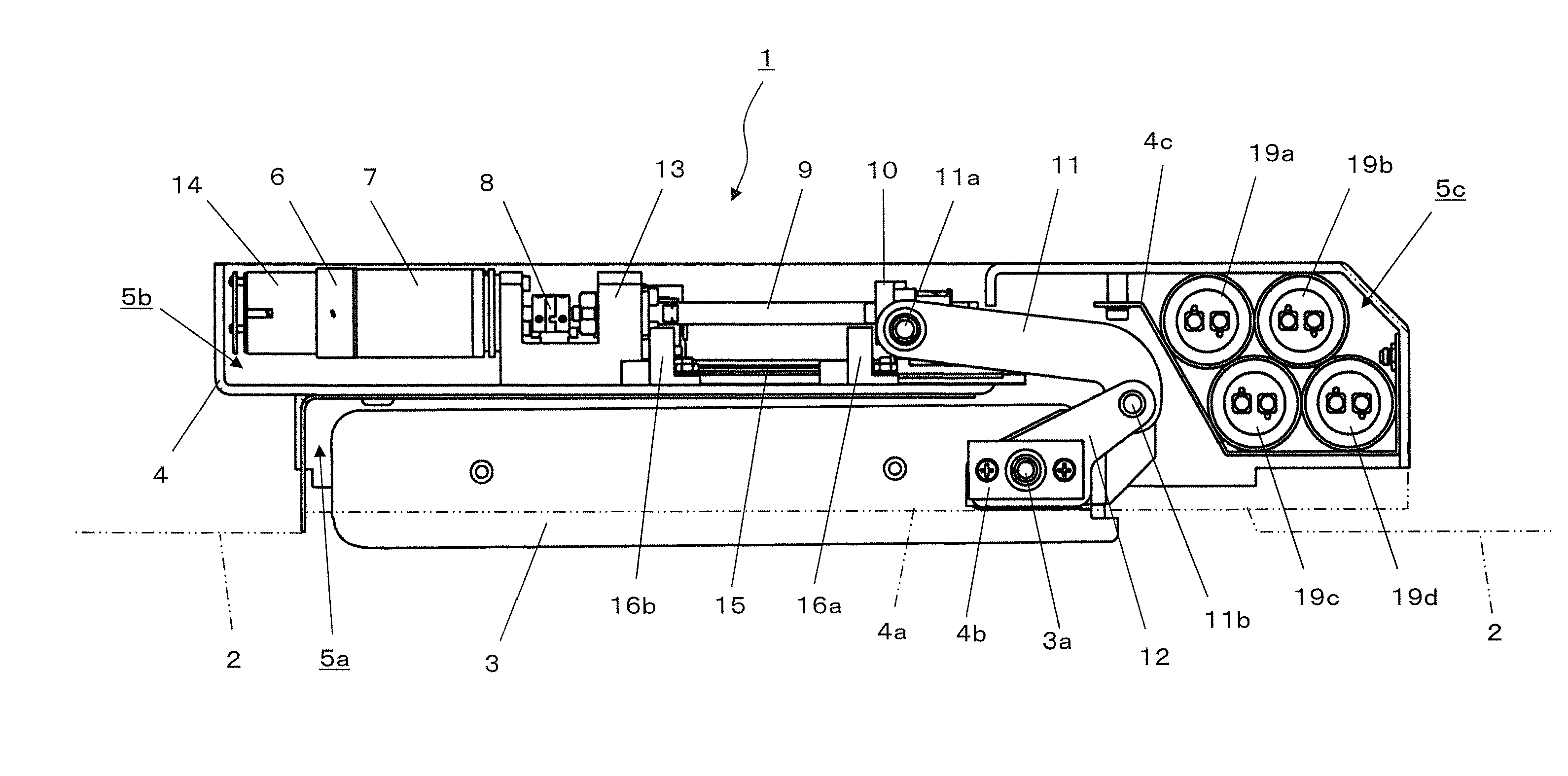
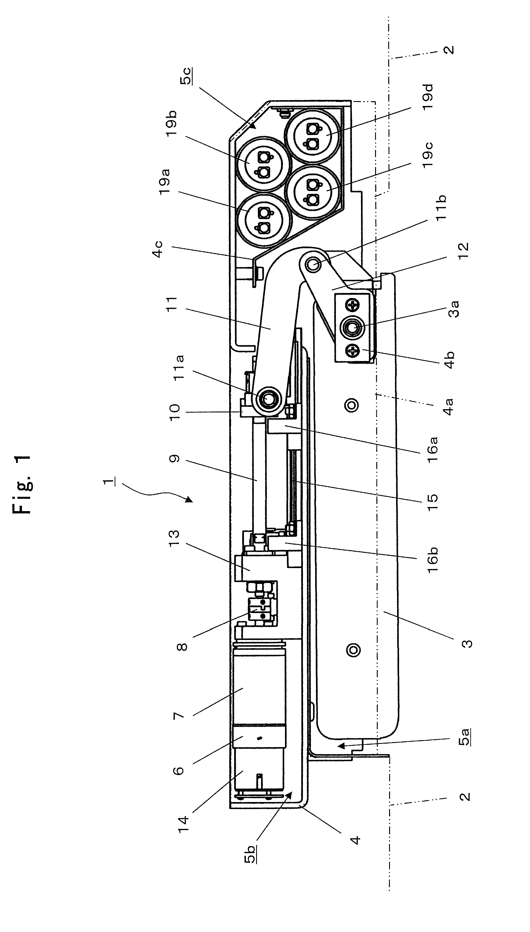
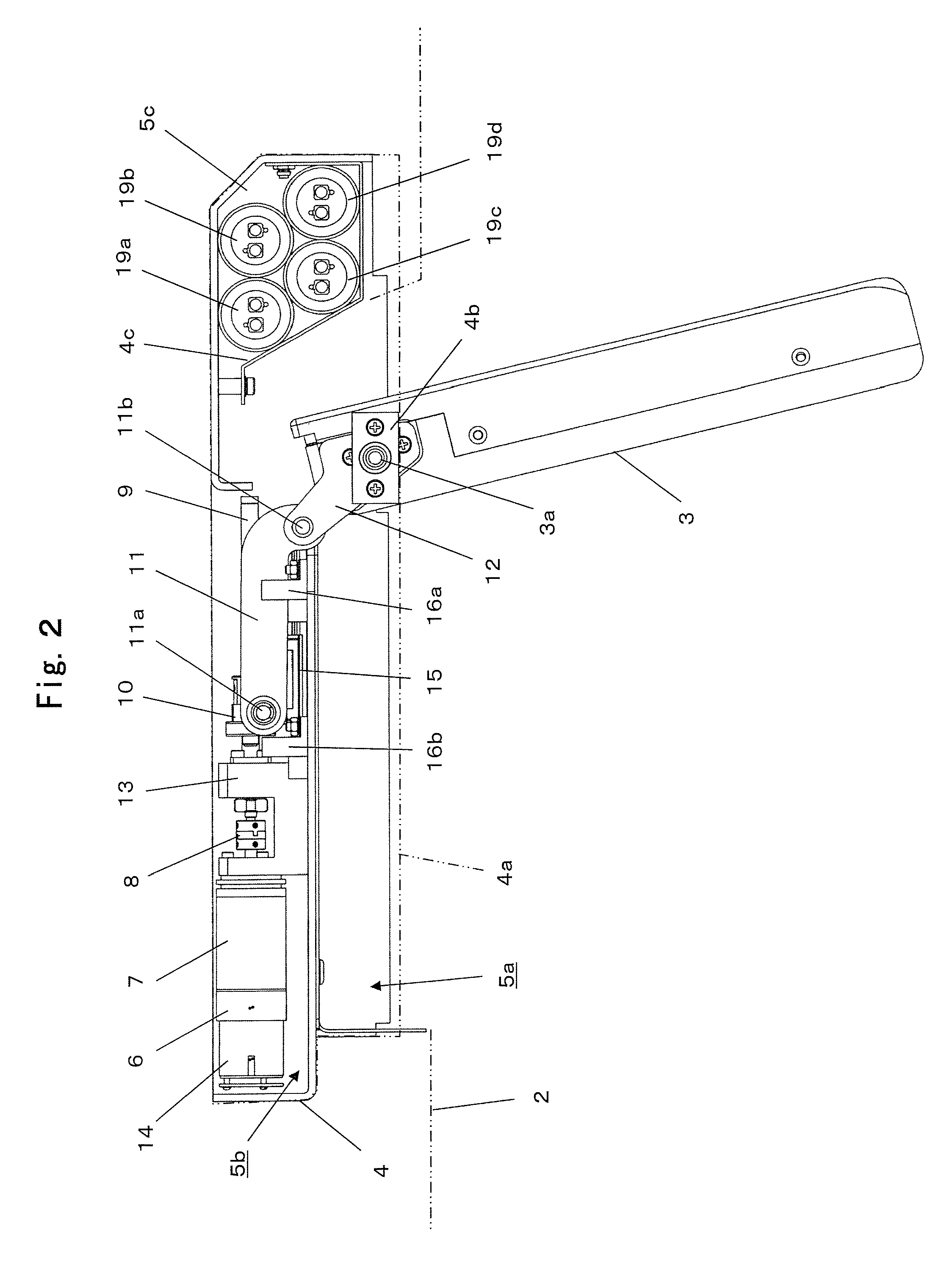
[0034]Preferred embodiments of the present invention, that is, a pivoting display device for use in aircraft will be described with reference to the drawings.

[0035]In the embodiment shown in FIGS. 1 to 5, the pivoting display device 1 is fixed to the PSU rail (not shown in figures) under the baggage rack / compartment in the ceiling area of the cabin of the aircraft. It is configured to enable a monitor 3 with a LCD unit to pivot open to the display position. The monitor 3 is supported by a bearing portion 4b that is attached and integrated into a chassis plate 4a of a chassis 4 that compose the entire device thereby enabling it to pivot around a shaft 3a. The chassis 4 serves also as a housing that composes the entire device. The said chassis comprises a stowing portion 5a, and also a stowing portion 5b which on its upper surface stows a motor 6, a gear transmission mechanism and circuit parts etc. for swinging the monitor 3. Here, in FIGS. 1 to 4, the chassis plate 4a covering the s...


PUM


Abstract

A pivoting device especially useful in aircraft passenger cabins that can pivot a monitor between stowed and open positions, the pivoting device including a forward / reverse rotatable driving motor. An electromagnetic brake holds the monitor in stowed and opened positions A power unit powers the motor and the electromagnetic brake. A controller controls the pivoting movement of the monitor. The power unit includes a rectifier circuit that transforms AC to a DC, a step-up circuit that steps up the transformed voltage, a voltage regulator that adjusts the transformed voltage to a prescribed DC voltage, and a retraction power retention circuit including a capacitor. When no source voltage is detected while the monitor is in its opened state, the capacitor supplies the power to a voltage regulator of the power circuit, deactivates the electromagnetic brake and reverse rotates the motor to drive the monitor to its stowed position.

Description

BACKGROUND OF THE INVENTION[0001]1. Field of the Invention[0002]The present invention relates to the improvement of a pivoting display device that comprise a video monitor that is used over the head of a passengers especially in aircraft and that can pivot the monitor open from its stowage position to its display position.[0003]2. Description of the Background Art[0004]Many passenger aircraft are provided with video monitors for every 2-3 rows of passenger seats to show and play movies, information about the flight and other similar material to passengers. These monitors are usually fixed to Passenger Service Unit (PSU) rails attached under the overhead baggage rack / compartment above the passenger seat. Said monitors are attached so that they can be swung open downwards to the display position and can be stowed back after their use. These devices are also provided with an electric motor and a drive mechanism that conveys the motor's rotating force. It is desirable that this pivoting...

Claims


Application Information

Patent Timeline
Patent Type & Authority Patents(United States)
IPC IPC(8): H04N5/64A47B5/00
CPCF16M13/02F16M11/10B64D11/0015B64D11/00F16M11/18
Inventor SUGIMOTO, YUKIOKATOH, HIRONORINAKAMURA, KOJI
Owner AIRCRAFT CABIN SYST
Why Eureka
Eureka Blog
Learn More