Handling machine for handling rails and handling process thereof

a technology of rails and handling machines, applied in the field of rail handling machines, can solve the problems of rail deflection or bending, high energy consumption, low efficiency, etc., and achieve the effect of avoiding damage to the external surface of the rail and the handlers, and effectively surviving deflection and its variations

Active Publication Date: 2014-03-11
DANIELI & C OFF MEC SPA
View PDF7 Cites 2 Cited by
  • Summary
  • Abstract
  • Description
  • Claims
  • Application Information

AI Technical Summary

Benefits of technology

[0015]It is the main object of the present invention to provide a handling machine for handling rails arranged in line and immediately downstream of a rolling plant, which allows an optimal clamping of the rail along its longitudinal extension, thus effectively withstanding the deflection and its variations while allowing a longitudinal movement of the rail caused by thermal shrinkage, thus avoiding damages both to the external surface of the rail and to the handlers.
[0029]The handling machine and process for handling rails of the present invention also advantageously has the following advantages:
[0030]a better clamping of the bent rail, while exerting relatively low clamping forces during the thermal quenching treatment in the tank, due to the fact that the application point of the forces generated by clamping the clamps on the bent rail flange is substantially aligned with the rotation fulcrums of the clamps themselves;
[0034]The handling, machine and process are inserted in a thermal treatment plant layout which includes using three cooling tanks with the following advantages:
[0035]it allows to obtain high production rates in terms of rails treated per unit of time;

Problems solved by technology

This implies the need to stock the rolled rails and then heat them before proceeding with the thermal quenching treatment, with high energy consumption and low efficiency.
In particular, if the immersion tank is used, cooling is more uniform lengthwise, but in all cases the temperature difference between the base of the hot rail and the cooled head results in the rail deflection or bending.
These variations of the longitudinal profile of the rail, more accentuated at the ends, cause the exertion of high vertical forces on the rail handler clamps; these forces could cause the clamps themselves to open with the consequent rail drop.
The clamps of the prior art have the disadvantage of being unsuitable for withstanding and containing said deflection and its variations during the thermal treatment.
On one hand, these forces ensure a good clamping of the rail while it is being moved and transferred close to the cooling tank, but on the other hand they hinder the longitudinal movement of the rail caused by thermal shrinkage that the rail itself undergoes when it is cooled down.
This shortening may cause damages both to the rail surface and to the handlers themselves due to the high clamping forces of the clamps on the rail.

Method used


Image

  • Handling machine for handling rails and handling process thereof
  • Handling machine for handling rails and handling process thereof
  • Handling machine for handling rails and handling process thereof

Examples


first embodiment

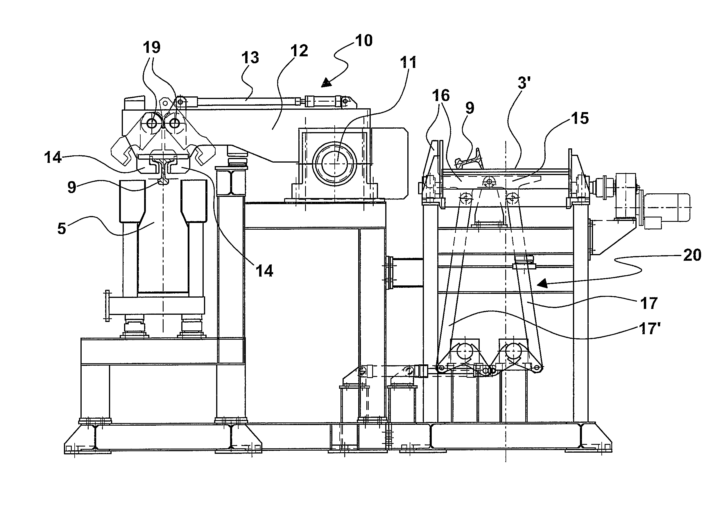
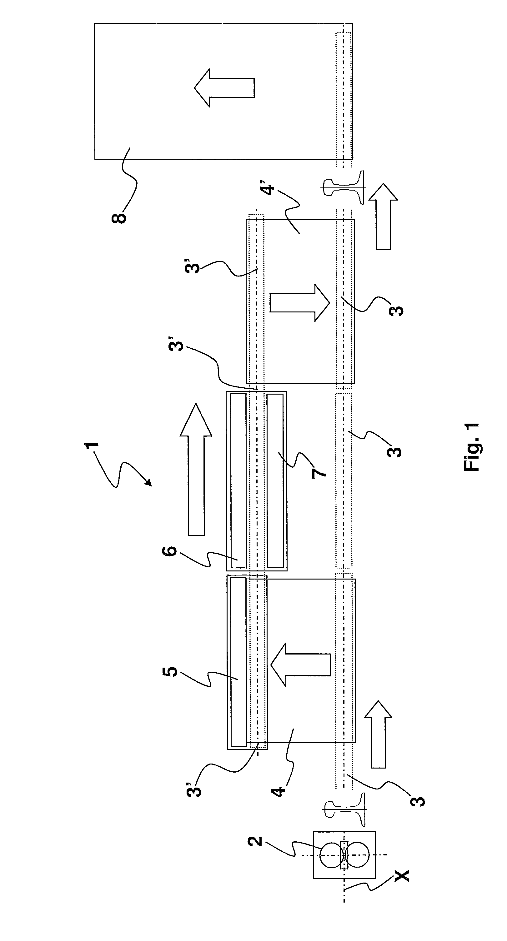
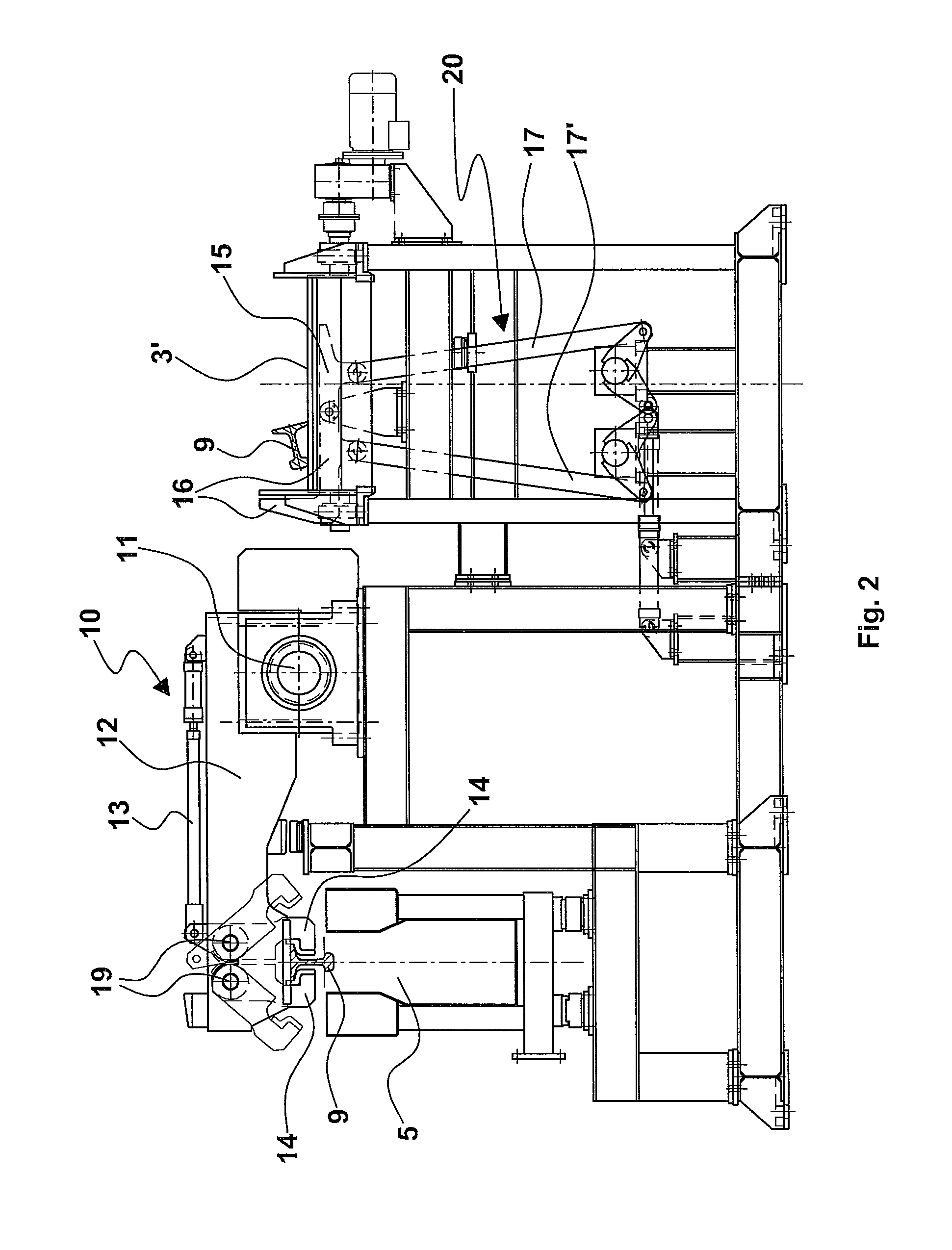
[0063]The process of handling the rails implemented using the aforesaid first embodiment of the handling machine comprises the following steps:[0064]1) unloading a rail 9 onto the roller table 3′ in an inclined position on one side and arranged laterally with respect to the longitudinal midline plane of the roller table 3′ itself; during this step of receiving the rail, the plates 15, 16 of the tilting means 20 are aligned so as to define a L-shaped cross section as a whole having the longer arm substantially parallel to the plane defined by the roller table 3′ (FIGS. 2, 2c);[0065]2) actuating the plates 15 so that they rotate by 90° in a first rotation direction about the pin 22 and the plates 15 and 16 define a substantially U-shaped cross section as a whole, within which the rail 9 is in an inclined position (FIG. 2d);[0066]3) actuating the plates 15 and 16 so that they integrally rotate by 90° in a second rotation direction opposite to the first about the pin 22, and that the ra...

second embodiment

[0118]The main advantage achieved by this second embodiment of the handling machine is represented by a production rate of 27 rails / hour and an hourly production rate of 180 tons / hour.

[0119]The thermal treatment cycle which is carried out in the quenching area, i.e. in the zone comprising the roller table 3′ and the cooling tanks, last for about 130 seconds / rail. The whole process cycle, from unloading onto the roller table 3 at the outlet of the last rolling mill stand to unloading again onto the same roller table 3 after completing the thermal treatment, lasts for 270 seconds.


PUM

PropertyMeasurementUnit
surface temperatureaaaaaaaaaa
temperatureaaaaaaaaaa
depthaaaaaaaaaa

Abstract

A handling machine for handling rails, arranged in line immediately downstream of a rolling plant, which allows an optimal clamping of the rail along its longitudinal extension, thus effectively withstanding the deflection and its variations, while allowing a longitudinal movement of the rail caused by thermal shrinkage, thus avoiding damages both to the external surface of the rail and to the handlers. A process of handling the rail is also described, which optimizes moving, positioning along a roller table and maintaining the rail substantially rectilinear during the thermal treatment to which it is subjected.

Description

FIELD OF THE INVENTION[0001]The present invention relates to a rail handling machine, in particular to a machine suitable for handling at least one rail in a thermal treatment plant for rail heads, said thermal treatment plant being arranged in line and immediately downstream of a rolling plant, and also relates to a rail handling process thereof.STATE OF THE ART[0002]The prior art embeds various solutions of systems for thermally treating rolled rails, in particular for hardening the head by means of quenching operations.[0003]Many of these systems are not arranged immediately at the rolling mill outlet. This implies the need to stock the rolled rails and then heat them before proceeding with the thermal quenching treatment, with high energy consumption and low efficiency.[0004]In other solutions, instead, these systems are arranged downstream of the rolling mill: the rolled rail is unloaded onto a roller table fixed to the ground; it is then picked up by handlers, comprising compl...

Claims


Application Information

Patent Timeline
Patent Type & Authority Patents(United States)
IPC IPC(8): C21D1/00
CPCC21D1/63C21D9/0018C21D2221/02C21D9/06B21B39/24
Inventor POLONI, ALFREDOSCHREIBER, MARCOANDREATTA, DANIELE
Owner DANIELI & C OFF MEC SPA
Why Eureka
Try Eureka