Metallic nanoparticle pressure sensor

a nanoparticle and pressure sensor technology, applied in the field of electromechanical sensors, can solve the problems of increasing the resistance between electrodes and achieve the effects of increasing the tunneling current, and reducing the tunneling

Inactive Publication Date: 2014-03-11
SHARP KK
View PDF7 Cites 40 Cited by
  • Summary
  • Abstract
  • Description
  • Claims
  • Application Information

AI Technical Summary

Benefits of technology

[0008]Disclosed herein is a resistive type pressure sensor, enabled through the flow of tunneling current between metal nanoparticles that are closely spaced apart in liquid or gas environment. When the density of the medium is changed due to an applied external pressure, the metal particles move closer together, forming a conductive path. The resistance between the two conducting electrodes is altered due to increased tunneling current. When the external pressure is released, the particles move away from each other, reducing the tunneling effect, and ultimately increasing the resistance between electrodes.
[0011]Accordingly, a method is provided for measuring pressure applied to a sensor surface. The method provides an electrical pressure sensor including a sealed chamber with a top surface, first electrode, second electrode, an elastic polymer medium, and metallic nanoparticles distributed in the elastic polymer medium. When the top surface of the sensor is deformed in response to an applied pressure, the elastic polymer medium is compressed. In response to decreasing the metallic nanoparticle-to-metallic nanoparticle mean distance between metallic nanoparticles, the electrical resistance is decreased between the first and second electrodes through the elastic polymer medium.

Problems solved by technology

When the external pressure is released, the particles move away from each other, reducing the tunneling effect, and ultimately increasing the resistance between electrodes.

Method used


Image

  • Metallic nanoparticle pressure sensor
  • Metallic nanoparticle pressure sensor
  • Metallic nanoparticle pressure sensor

Examples


Embodiment Construction

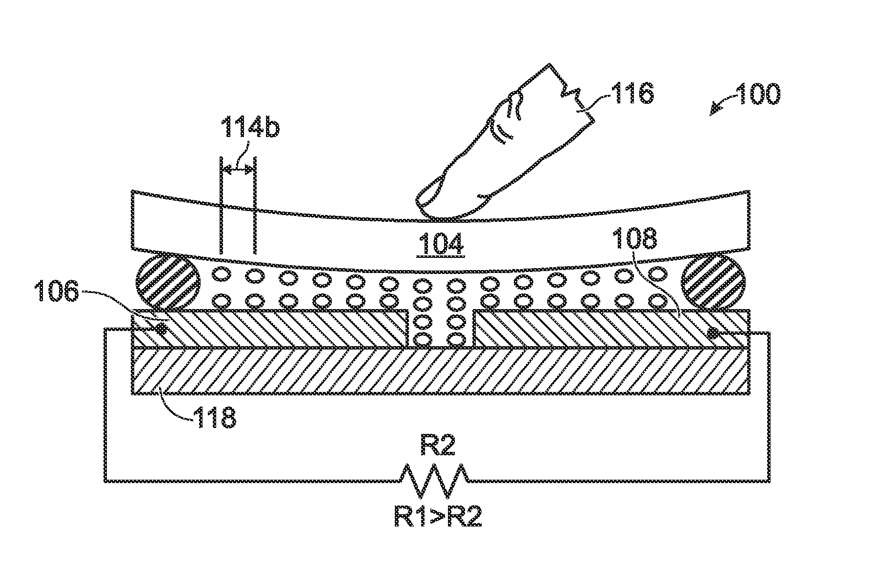
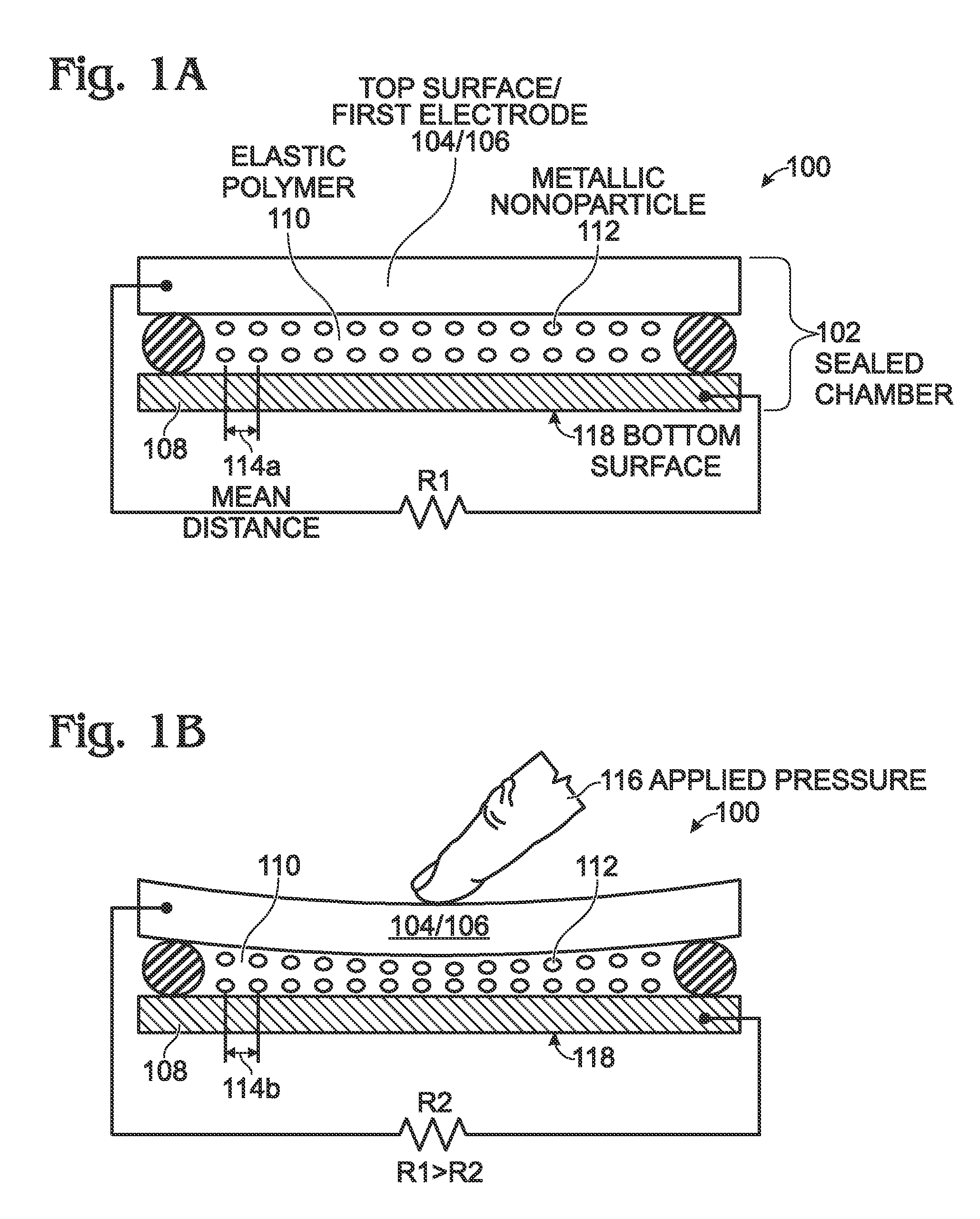
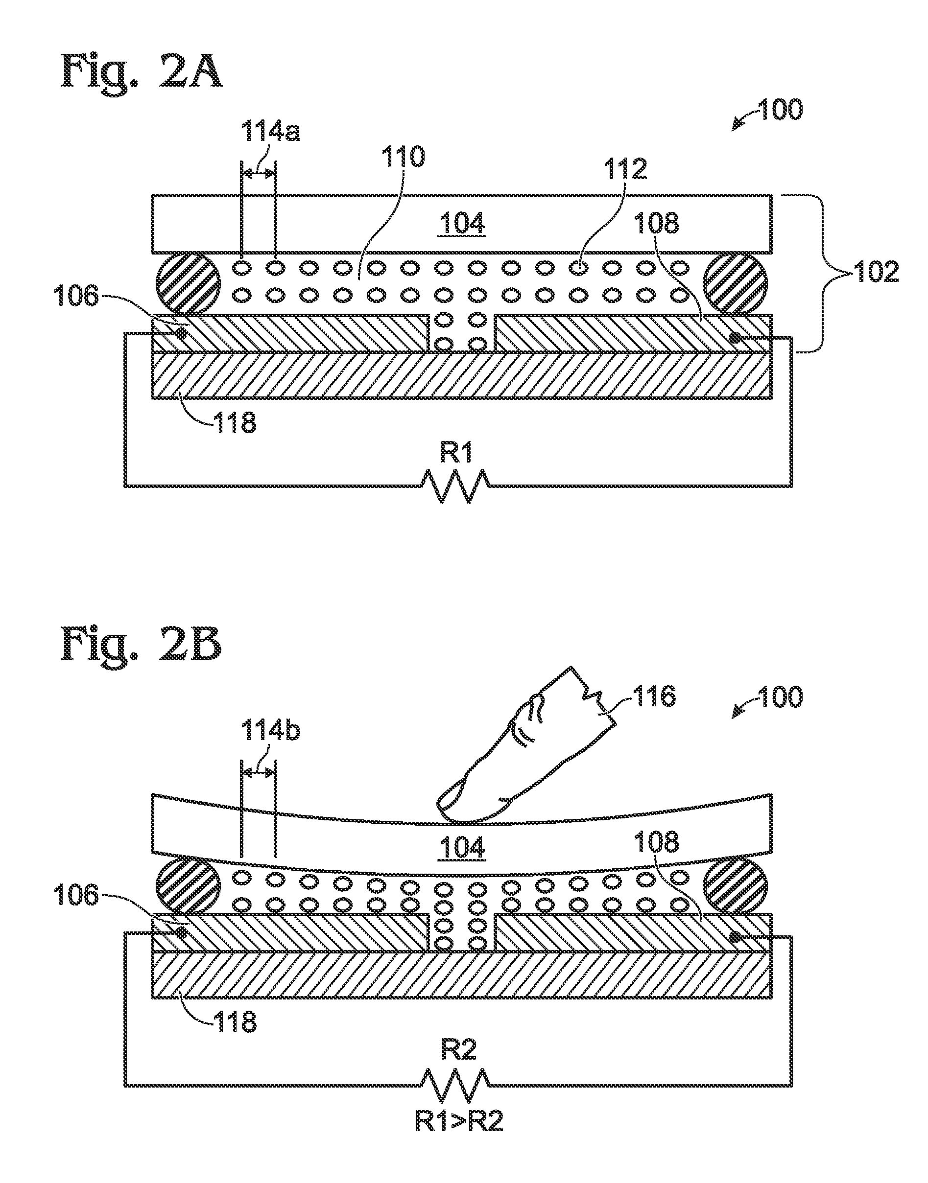
[0028]FIGS. 1A and 1B are partial cross-sectional views of a pressure sensor. The pressure sensor 100 comprises a sealed chamber 102 with a top surface 104, a first electrode 106, and a second electrode 108. An elastic polymer medium 110, with distributed metallic nanoparticles 112, at least partially fills the sealed chamber 102. The nanoparticles may be randomly distributed or formed in an array. The elastic polymer medium 110 is in contact with the first electrode 106 and the second electrode 108 when the top surface 104 is deformed by an applied pressure.

[0029]Contrasting FIGS. 1A and 1B, the metallic nanoparticles 112 have a metallic nanoparticle-to-metallic nanoparticle mean distance 114 that decreases in responsive to applied pressure 116 on the top surface 104. The result is decreased electrical resistance between the first electrode 106 and the second electrode 108 through the elastic polymer medium 110 (R1>R2). More explicitly, the figures depict that the sealed chamber 10...


PUM


Abstract

An electrical pressure sensor is provided with a method for measuring pressure applied to a sensor surface. The method provides an electrical pressure sensor including a sealed chamber with a top surface, first electrode, second electrode, an elastic polymer medium, and metallic nanoparticles distributed in the elastic polymer medium. When the top surface of the sensor is deformed in response to an applied pressure, the elastic polymer medium is compressed. In response to decreasing the metallic nanoparticle-to-metallic nanoparticle mean distance between metallic nanoparticles, the electrical resistance is decreased between the first and second electrodes through the elastic polymer medium.

Description

BACKGROUND OF THE INVENTION[0001]1. Field of the Invention[0002]This invention generally relates to electronic sensors and, more particularly, to a pressure sensitive sensor fabricated using metallic nanoparticles embedded in an elastic polymer medium.[0003]2. Description of the Related Art[0004]Pressure sensors are one of the most common type sensors used today. A pressure sensor acts as a transducer, generating a signal that is a function of the force imposed, to measure strain due to applied pressure over a certain area. Many types of transducers currently exist including piezoresistive, capacitive, electromagnetic, piezoelectric, and optical types. A pressure sensor can also measure change in density of fluid or gas, to gauge environmental pressures. Some examples include pressure sensors designed to measure a change of resonant frequency using micro electromechanical system (MEMS), the thermal change of heated filament, i.e. pirani gauge, or the flow of charged ionic gas partic...

Claims


Application Information

Patent Timeline
Patent Type & Authority Patents(United States)
IPC IPC(8): B25B23/14G01L5/24G06F3/041
CPCG01L1/20B82Y15/00G06F3/045
Inventor HASHIMURA, AKINORITANG, LIANGVOUTSAS, APOSTOLOS T.
Owner SHARP KK
Why Eureka
Try Eureka