
Method and device of turbine submerged combustion boiler

a technology of submerged combustion and boiler, which is applied in the direction of machines/engines, preheating, lighting and heating apparatus, etc., can solve the problems of limited exhausting pressure, high mechanical energy consumption, and low air utilization rate, and achieve the effect of improving energy efficiency

Inactive Publication Date: 2014-03-18
LI WEICHENG
View PDF4 Cites 2 Cited by
  • Summary
  • Abstract
  • Description
  • Claims
  • Application Information

AI Technical Summary

Benefits of technology

[0005]In view of the aforementioned drawbacks, the objective of the present invention is to provide a working method and device of submerged turbine combustion boiler utilizing the turbine heat engine principle, in order to improve the energy efficiency.
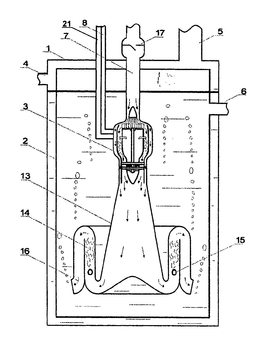
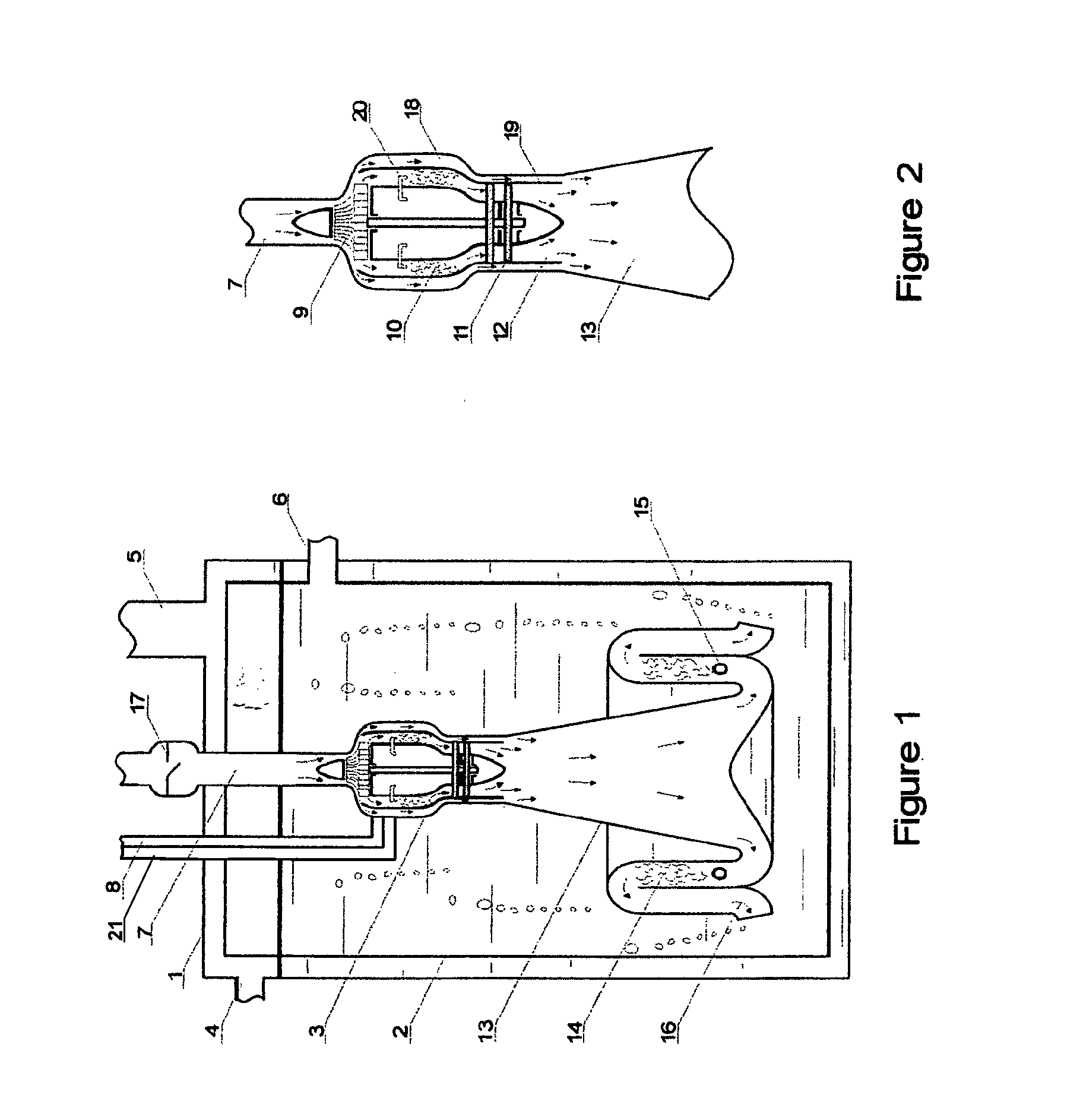
[0016]The external air channel is open to the outside; so as to allow cold air filling in the combustion chamber and the whole turbine as well. The air will be expelled to the pressurizing pipe unit directly. In this way, the scale deposition on the external surface of the combustion chamber and the associated heat dissipation problem can be avoided. The turbine power combustion assembly can be cooled down stably and reliably.
[0017]The terminal part of tail jet pipe unit is in either linear form or diffuser form. Normally, the tail jet pipe unit is designed as a reducer form in order to obtain high speed gas. For the turbine submerged combustion boiler of the present invention, such high speed gas is nonetheless not necessary. Hence it has been designed as linear or diffuser type, which will reduce the resistance and the energy consumption as well.
[0018]The invention, a working method and device of turbine submerged combustion boiler utilizing turbine heat engine principle, has the following advantages:(1) Low Heat Energy Loss
[0020]High temperature gas produced by the complete combustion will mix with the water and will exchange its heat with the water in the form of a large quantity of micro bubbles. In this way, there would be no area limitation and no heat resistance loss due to the sediment. Thus, it has a large heat exchanging area, short exchanging route and low heat resistance. With the large quantity of micro bubbles floating up in the water, it will lead to an intensive all-around stirring up effect. Thus, the heat exchanging is fast and effective. The most advantageous feature of the present invention is that the exhausted gas will finally have a temperature close to water temperature; suggesting the combustion heat utilization has been maximized.(3) Long Term Stable Heat Efficiency
[0023]Because such complex and huge heat exchanger has been avoided, the feeding water pre-treat system to prevent sediment can be simplify or even omitted. The air blowing equipment to supply combustion-assistant air as well as the gas purification equipment are both saved. This new type of boiler device has the beneficial features of simple equipment structure, small occupying space, low system cost, and low maintenance cost, etc.

Problems solved by technology

But because it used a piston type engine burner and a direct-jet heat exchange method, the invention disclosed in this patent has the disadvantages of high mechanical energy consumption, limited exhausting pressure, low air utilizing rate, etc.

Method used


Image

  • Method and device of turbine submerged combustion boiler
  • Method and device of turbine submerged combustion boiler

Examples


Embodiment Construction

[0029]As shown in FIGS. 1 and 2, the turbine submerged combustion boiler of the present invention, including water tank 1, cold water inlet 4 and gas exhaust port 5 on top of water tank 1, flow guide cylinder 2 within water tank 1, hot water outlet 6 on the flow guide cylinder 2, turbine power combustion assembly 3 in the flow guide cylinder. Turbine power combustion unit 3 is connected with air intake pipeline 7 and fuel and assistant-materials pipeline 8 at the top. Inside turbine power combustion assembly 3, along the flow direction, there are an air compressor unit 9, a combustion chamber 10, an external air channel 18, a turbine 11, and a tail jet pipe unit 12. The pressurizing pipe unit 13 is connected with the outlet of the tail jet pipe unit 12 and outlet of external air channel 18. The secondary combustion chamber 14 is connected with the end of the pressurizing pipe unit 13. In the secondary combustion chamber 14, there are a replenishing fuel nozzle 15, and the guide exha...


PUM


Abstract

The invention is about a submerged combustion method and the device; specifically, it is a submerged combustion method and the device utilizing turbine heat engine principle. In the invention, turbine power combustion means is used and substitutes the conventional submerged combustion system that must equip air blowing means. The high temperature gases generated from the combustion within the turbine power combustion means will do work on the turbine, which will drive the air compressor means of the turbine power combustion means to induce air for combustion, and will drive the second-time complete combustion of high temperature gases and the complement fuel, and then the gases will come out from water bottom against tank water pressure and carry out heat interchange with tank water. The turbine submerged combustion boiler device of the invention need not equip air blowing means which would consume additional energy. Thus, it has high energy efficiency and a simple system structure. Additionally, it has features of high heat interchange rate, stable long term heat efficiency, environmental protection, etc.

Description

FIELD OF THE INVENTION[0001]The present invention is about a submerged combustion method and device, and more particularly, it is a submerged combustion method and device utilizing turbine heat engine principle.BACKGROUND OF THE INVENTION[0002]Submerged combustion method, which is also referred to as in-liquid combustion method, is a new type of combustion technology. Fuel and air are fully mixed and fed into combustion chamber for complete combustion, and the generated high temperature gas is expelled into liquid directly to heat up the liquid. The combustion process of submerged combustion method implements a heat transfer process that is a direct-contact heat transfer process.[0003]As a high efficiency heat transfer method, submerged combustion method has been used in such industries as chemical industry, etc. Due to the fact of its high heat transfer efficiency comparing to other heat transfer methods, both domestic and international thermal energy industries started to focus on...

Claims


Application Information

Patent Timeline
Patent Type & Authority Patents(United States)
IPC IPC(8): F02G5/02
CPCF02C3/14F02C6/18F02C3/08F22D1/28
Inventor LI, WEICHENG
Owner LI WEICHENG
Learn More