
Microplasma ion source for focused ion beam applications

a microplasma ion source and focused ion beam technology, applied in the field of focused ion beam (fib) systems and methods, can solve the problems of reducing the dimensions of all of the ic components, affecting the use of ga+/sup> ions in ce applications, and increasing the complexity of ic technology

Inactive Publication Date: 2014-03-18
TIZA LAB
View PDF32 Cites 1 Cited by
  • Summary
  • Abstract
  • Description
  • Claims
  • Application Information

AI Technical Summary

Benefits of technology

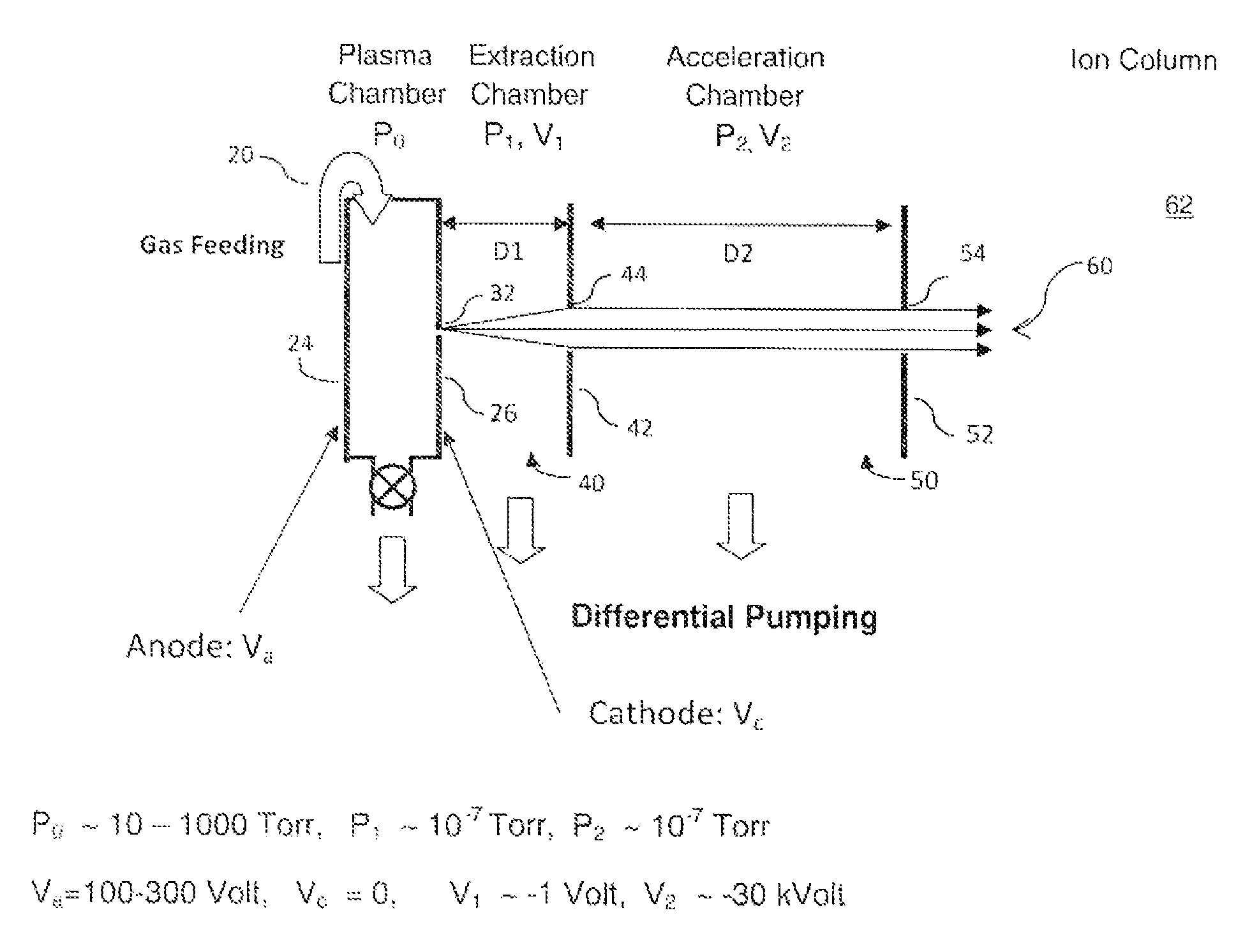
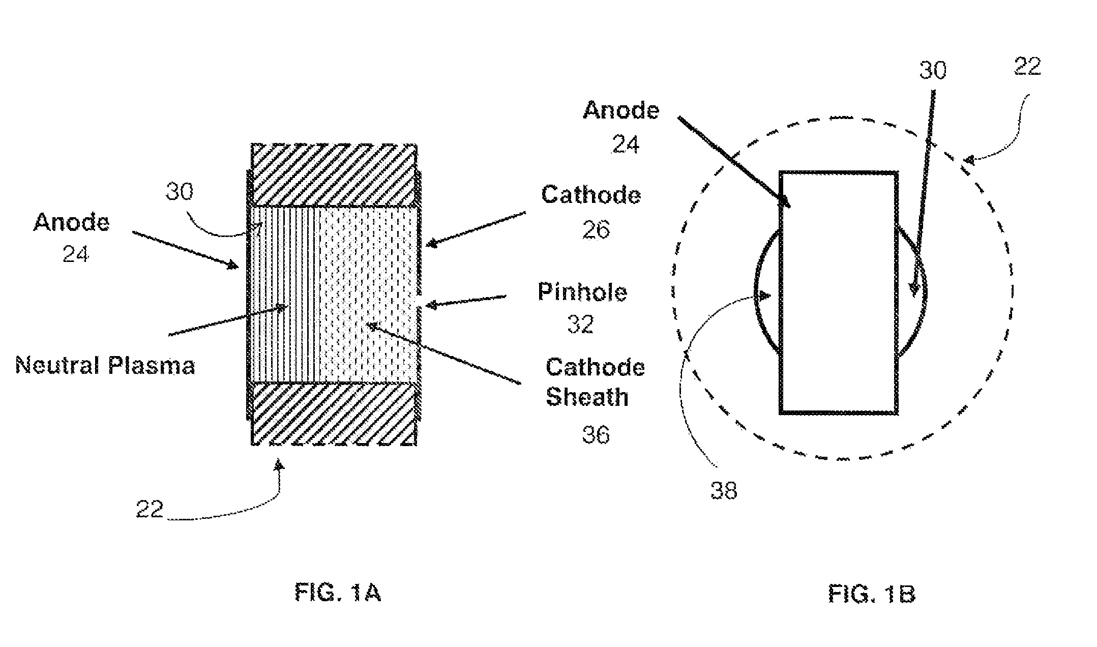
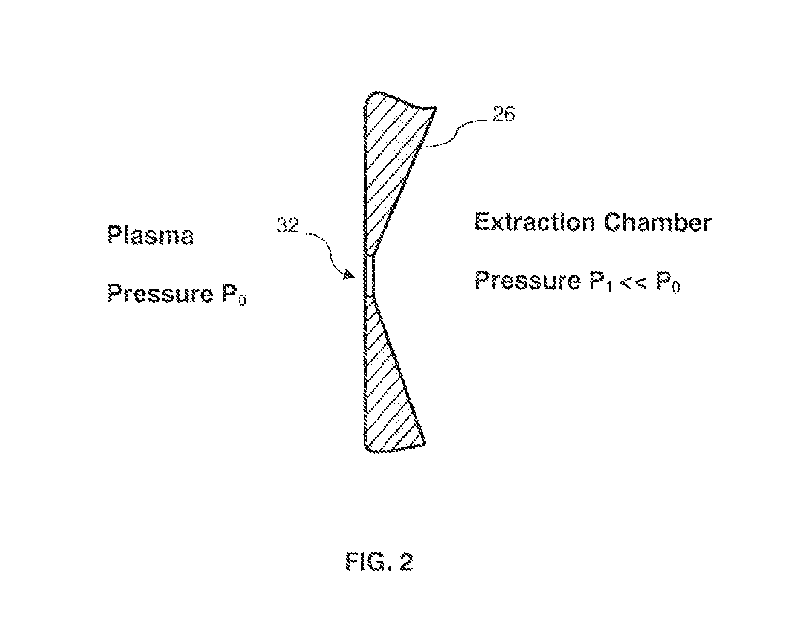
[0010]In one aspect, the invention recognized that the foregoing and other problems associated with conventional plasma sources in obtaining a suitable bright, low temperature source of positive ions with narrow energy spread for FIB operations can be avoided by using a high pressure normal glow discharge microplasma (microdischarge) to ionize a suitable working gas to produce the ions. Microplasma sources operating in the normal glow discharge regime at high (hundreds of Torr) pressure have not previously been used to produce ions for FIB applications. A microplasma source has a small (microscopic sized) plasma chamber with linear sizes on the order of 1 μm-1000 μm or so in all three dimensions, and can operate in the normal glow discharge regime at plasma pressures up to 1000 Torr or higher to produce a flux of ions with a low energy spread not exceeding approximately 2.4 eV, which is approximately full width at half maximum (FWHM) of a Boltzmann energy distribution function at an average energy 1 eV. In a normal glow discharge, current density is proportional to the square of the gas pressure. Thus, the current density in a microplasma can be continuously adjusted from a low of the order of about 10−2 A / cm2 to a high of the order of about 1 A / cm2 or greater by controlling the gas pressure. Additionally, the current in the circuit controlled by using a regulated power supply and a ballast resistor. Accordingly, these techniques allow a desired ion current to be extracted from a small pinhole opening in the cathode, the opening having size in the range of about 10 nm-2000 nm.

Problems solved by technology

Although current LMIS technology has the ability to focus a Ga+ ion beam down to nanometer scale, the use of Ga+ ions is becoming problematic for CE applications on more advanced ICs.
First, as IC technology is moving towards increasing complexity, the dimensions of all of the IC components scale down.
This damage can compromise the ability of the IC to work properly after such a modification.
Secondly, since Ga is a conductive metal, the implantation of Ga+ ions can cause electrical short circuiting of the IC layers to each other or other malfunctioning of the IC.
However, previous attempts to use a plasma source for forming a focused Xe+ or Xe2+ ion beam have not been successful because of the inability to obtain an ion beam with a suitable current density that can be focused down to the required nanometer scale spot size, which is required for processing modern ICs.
Otherwise, either the FIB operation would proceed too slowly or the ion source size would have to be so large that fine focusing would not be possible.
At this current, the plasma would become unstable and unusable.
Otherwise, the ion energy spread would create chromatic aberrations that would excessively broaden the spot size of the focused beam and make it unusable for CE on newer ICs.
Therefore, in order to obtain a current density of about 1 A / cm2, a normal glow discharge in Xe would have to operate at a very high pressure of about 300 Torr or greater, which is impractical.
In conventional macroscopic (i.e., geometric sizes approximately 1 cm) plasmas, normal glow discharges cannot be sustained at such high pressures and high current densities.
Moreover, the AGD regime at high currents is susceptible to instabilities and, in particular, to constriction and arcing (glow-to-arc transition).

Method used


Image

  • Microplasma ion source for focused ion beam applications
  • Microplasma ion source for focused ion beam applications
  • Microplasma ion source for focused ion beam applications

Examples


Embodiment Construction

[0016]In order to obtain a cold (normal glow discharge ion temperature in the range of 0.5-1 eV), bright (current density in the range of 0.1-1 A / cm2 or higher) flux of positive ions of a suitable gas, for example an inert noble gas, such as xenon, for use in focused ion beam (FIB) applications, the invention uses a high pressure normal glow discharge microplasma source, preferably having a parallel plate geometry. However, unlike macroscopic plasma sources having sizes of the order of 1 cm and which cannot sustain normal glow discharges at high pressures and high current densities, the microplasma sources used by the invention have chamber dimensions of about 1-1000 μm, and can sustain normal glow discharge over a wide range of gas pressures and electrical currents, and more particularly at high gas pressures and currents in the desired ranges. Microplasma sources which may be used to practice the invention comprise devices having various different architectures, geometries, and el...


PUM

PropertyMeasurementUnit
pressureaaaaaaaaaa
current densityaaaaaaaaaa
pressureaaaaaaaaaa

Abstract

The present invention provides a method of obtaining a bright source of ions with narrow energy spread for focused ion beam applications using micro plasmas. As a preferred embodiment, a high pressure microplasma source operating in a normal glow discharge regime is used to produce a cold bright focused beam of Xe+ and / or Xe2+ ions having ion temperature of the order of 0.5-1 eV and a current density on the order of 0.1-1 A / cm2 or higher.

Description

CROSS REFERENCE TO RELATED APPLICATIONS[0001]This application is a continuation-in-part of U.S. application Ser. No. 13 / 407,549, filed Feb. 28, 2012 now U.S. Pat. No. 8,481,966.BACKGROUND[0002]This invention relates generally to focused ion beam (FIB) systems and methods, and more particularly to a low temperature bright microplasma ion source for FIB applications.[0003]Focused ion beam processes are widely used in the semiconductor industry for applications such as integrated circuit (IC) circuit editing (CE) and for debugging and verification of the functionality of ICs. Circuit editing involves modification of individual IC circuits in order to correct design or manufacturing errors that cause IC malfunctions. Currently, FIB systems use a finely focused beam of gallium ions that can be operated in a range of beam currents from several pico-Amperes (pA) up to tens of nano-Amperes (nA). Gallium ion beam technology uses a liquid metal ion source (LMIS) that enables a Ga+ ion beam to...

Claims


Application Information

Patent Timeline
Patent Type & Authority Patents(United States)
IPC IPC(8): H01J27/26A61L2/14H01J37/317H01J49/16H01J37/32H01J37/08H01J49/40
CPCH01J27/205H01J49/167H01J27/26H01J37/3171H01J37/32018H01J37/08H01J2237/0815H01J2237/0817H01J2237/31749
Inventor MAKAROV, VLADIMIR V.MACHERET, SERGEY
Owner TIZA LAB
Learn More