
Electrical feedthrough of a capacitor for medical implants and method for the production and use thereof

a technology of medical implants and capacitors, which is applied in the direction of electrolytic capacitors, electrotherapy, therapy, etc., can solve the problems of contaminating the interior of the device in which they are installed, the capacitor interior cannot be escaped (very slow), and the capacitor is difficult to manufacture, etc., to achieve the effect of reducing the risk of contamination, facilitating process control, and facilitating the subsequent soft soldering of the external terminal

Active Publication Date: 2014-03-18
BIOTRONIK SE & CO KG
View PDF10 Cites 9 Cited by
  • Summary
  • Abstract
  • Description
  • Claims
  • Application Information

AI Technical Summary

Benefits of technology

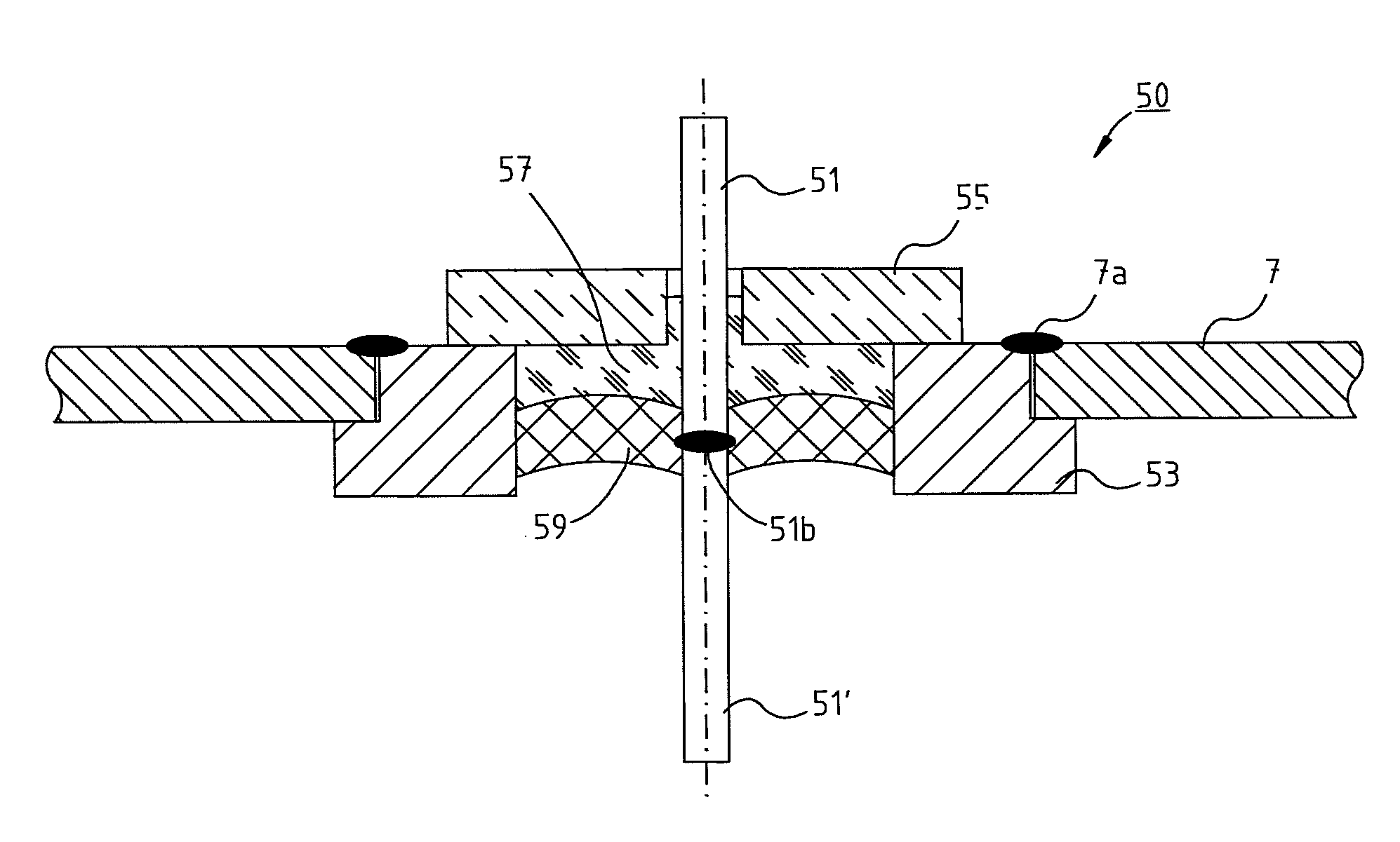
This patent describes a new design for a terminal pin used in electronic feedthroughs. The terminal pin has a core made of a material with the same or similar coefficient of thermal expansion as the glass solder, which helps to prevent high mechanical tension strains during production and usage. The interior of the terminal pin, which is important for electrochemistry, can be made of aluminum, which is compatible with the remainder of the electrolyte capacitor. The terminal pin can also be enclosed by a ceramic ring, which helps to form a hermetic seal with the glass solder plug and provides insulation against bending forces. The amount of glass solder and the effective sealing interface between the glass solder and the terminal pin are kept low to minimize tension between them.

Problems solved by technology

Such constructions have a seal made of rubber-like materials or plastics which, however, does not prevent an escape (very slow) of electrolyte components from the capacitor interior to the outside.
A restricted lifetime and reliability and the danger of contamination of the interior of the devices in which they are installed, i.e., especially the noted implants, are thus caused.
Constructions based on tantalum or niobium, so-called Ta—HV or Nb—HV capacitors, are also known, which are significantly more heavy than A1-HV capacitors, however, and whose production technology is difficult to control.

Method used


Image

  • Electrical feedthrough of a capacitor for medical implants and method for the production and use thereof
  • Electrical feedthrough of a capacitor for medical implants and method for the production and use thereof
  • Electrical feedthrough of a capacitor for medical implants and method for the production and use thereof

Examples


Embodiment Construction

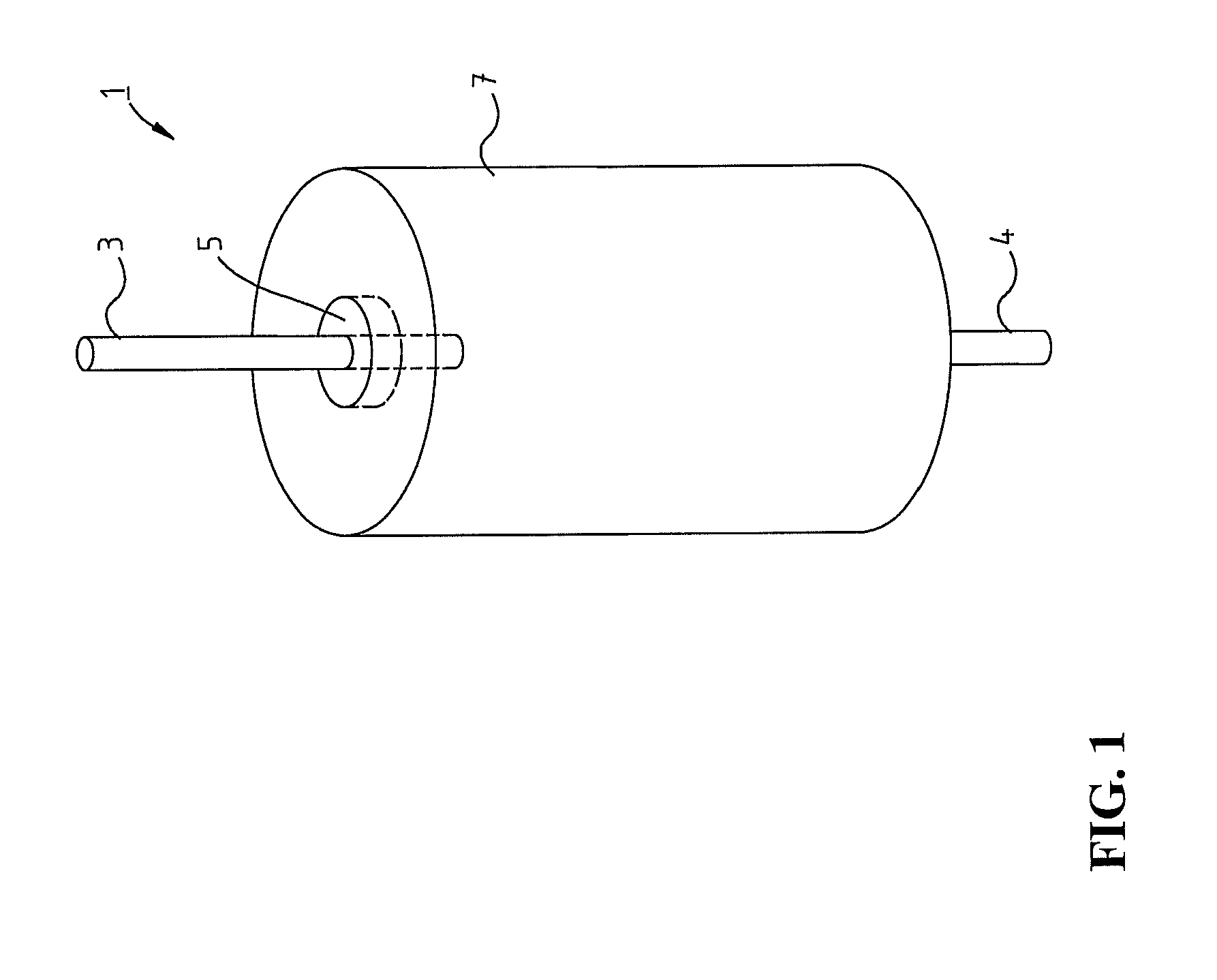
[0018]FIG. 1 shows a perspective illustration of a known construction of an electrolyte capacitor 1 having two terminal pins 3 and 4, and a feedthrough 5 being shown schematically outlined on a front side of a housing 7.

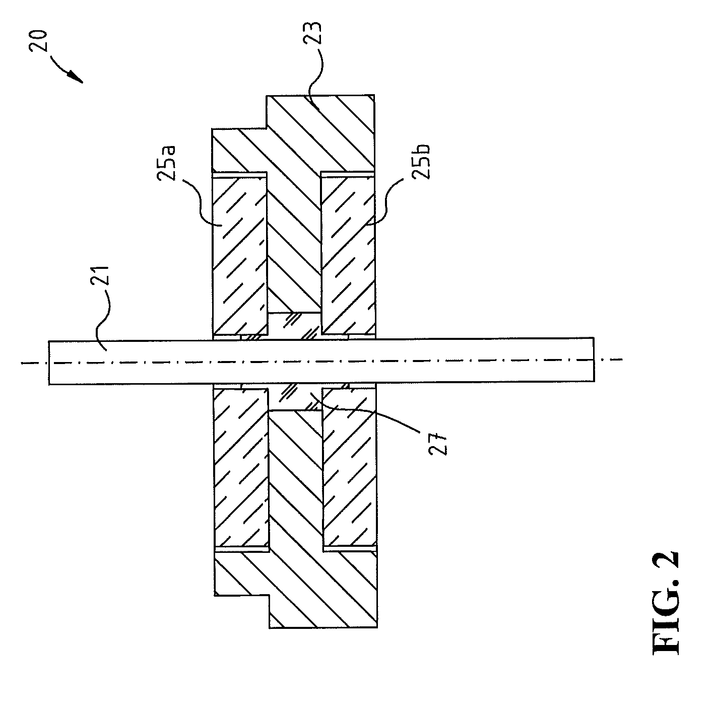
[0019]FIG. 2 shows, as an embodiment of the present invention, a feedthrough 20 having an aluminum terminal pin 21, an aluminum flange 23 provided on the top and bottom with flat cylindrical recesses, and ceramic discs 25a, 25b, each lying in the aluminum flange 23, and having a central opening for the passage of the aluminum pin 21. A housing wall (not shown here) adjoins the construction on the exterior of the aluminum flange 23, and a glass solder plug 27 is located between the central part of the aluminum flange 23 and the inner walls of the central openings of the ceramic discs 25a, 25b and the external surface of the pin 21, which hermetically seals both the pin 21 and also the aluminum flange 23 in relation to the surrounding surfaces, so that overall a hermet...


PUM

PropertyMeasurementUnit
melting temperatureaaaaaaaaaa
soldering temperatureaaaaaaaaaa

Abstract

A feedthrough of an electrolyte or other capacitor, in particular for use in a medical-electronic implant, is provided having a terminal pin which has a section which can be soft soldered at least in the interior of the electrolyte capacitor, an aluminum flange enclosing the terminal pin, and a glass solder plug which hermetically seals the terminal pin in relation to the aluminum flange.

Description

RELATED APPLICATION[0001]This patent application claims the benefit of co-pending U.S. Provisional Patent Application No. 61 / 318,403, filed on Mar. 29, 2010, which is hereby incorporated by reference in its entirety.TECHNICAL FIELD[0002]The present invention relates to a so-called feedthrough (the terminal pin area) of an electrolyte, tantalum, niobium, or other capacitor and, additionally, to a method for the production and use of such a feedthrough and a capacitor having such a feedthrough.BACKGROUND OF THE INVENTION[0003]Capacitors, such as electrolyte, tantalum, or niobium capacitors for use in medical-electronic implants, such as, for example, defibrillators, are known in various embodiments and in practical use. Constructions based on the aluminum foils for high-voltage applications, so-called A1-HV capacitors, are customary in entertainment electronics. Such constructions have a seal made of rubber-like materials or plastics which, however, does not prevent an escape (very sl...

Claims


Application Information

Patent Timeline
Patent Type & Authority Patents(United States)
IPC IPC(8): H01G4/35H01G4/236
CPCA61N1/3754Y10T29/49165
Inventor TESKE, JOSEF
Owner BIOTRONIK SE & CO KG
Learn More