
Methods for transmitting data in a mobile system and radio stations therefor

a mobile system and data technology, applied in the direction of transmission monitoring, frequency-division multiplex, receiver monitoring, etc., can solve the problems of high signalling load, failure to transmit codewords on beams, and inability to support transmission, so as to achieve the effect of not causing too much overhead

Active Publication Date: 2014-03-18
KONINKLIJKE PHILIPS ELECTRONICS NV
View PDF13 Cites 10 Cited by
  • Summary
  • Abstract
  • Description
  • Claims
  • Application Information

AI Technical Summary

Benefits of technology

[0019]It is an object of the invention to propose a method of signalling quickly available resources without causing too much overhead.
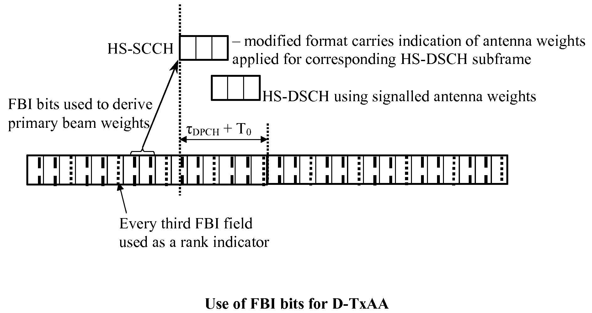
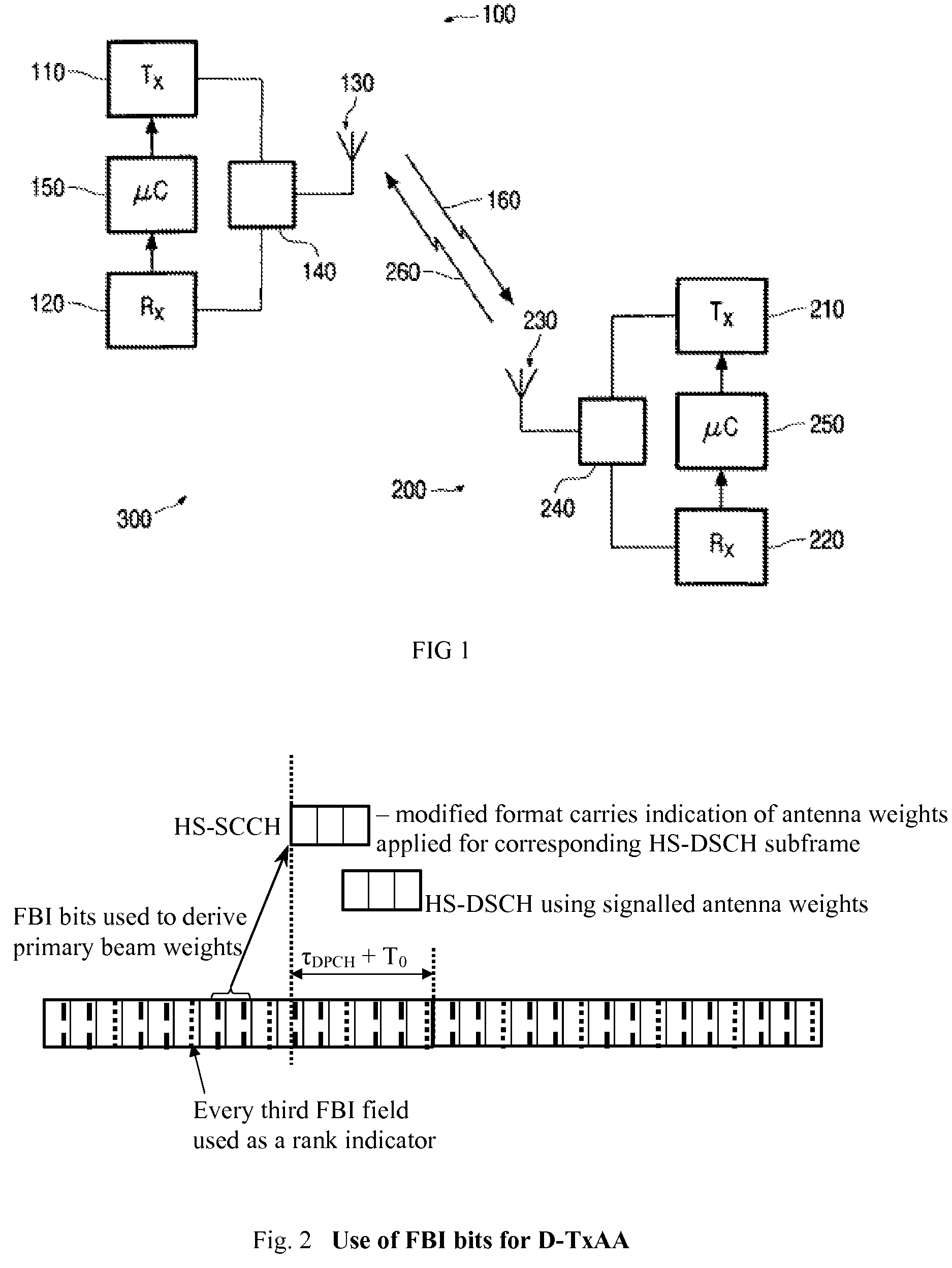
[0024]According to the invention, a fast rank indicator is signalled from the secondary station or User Equipment (UE) to the primary station or Node B to enable rapid adjustment of the number of simultaneously-transmitted codewords without requiring CQI to be transmitted every sub-frame. The indicator may only indicate the number of available data streams that can support a codeword. Thus, the size of this indicator is reduced and, even if this indicator is sent very frequently (in each frame or subframe), it does not lead to too much overhead.
[0025]As a consequence, this second indicator permits to have a flexible control of the number of codewords allocated to the set of datastreams, preventing thus the wasting of capacity, or problems of transmissions.

Problems solved by technology

However, frequent CQI reporting results in a high signalling load.
A reduced CQI reporting rate may be used, but the Node B will then be slower to react to changes in the rank of the channel, resulting in failed transmissions of codewords on beams, which cannot support transmission, or wasted capacity when beams are not used which could support a transmission.

Method used


Image

  • Methods for transmitting data in a mobile system and radio stations therefor
  • Methods for transmitting data in a mobile system and radio stations therefor

Examples


Embodiment Construction

[0034]The present invention relates to a system of communication 300 as depicted in FIG. 1, comprising a primary station 100, like a base station, and at least one secondary station 200 like a mobile station. More specifically, this invention can be applied in multi-antenna communication systems, and in particular, potential application is foreseen in the MIMO feature currently being standardised for UMTS Release 7.

[0035]The radio system 300 may comprise a plurality of the primary stations 100 and / or a plurality of secondary stations 200. The primary station 100 comprises a transmitter means 110 and a receiving means 120. An output of the transmitter means 110 and an input of the receiving means 120 are coupled to an antenna array 130, including at least two antennas, by a coupling means 140, which may be for example a circulator or a changeover switch. Coupled to the transmitter means 110 and receiving means 120 is a control means 150, which may be for example a processor. The seco...


PUM


Abstract

The present invention relates to a method for transmitting a plurality of data streams from a primary station to a secondary station on a plurality of transmission beams, said method comprising: at the secondary station measuring the channel quality corresponding to each transmission beam, and signalling at a first rate to the primary station in a first indicator a CQI report representative of the quality of the beams, and signalling at a second rate, greater than the first rate, in a second indicator a number of data streams that can be transmitted on the transmission beams; at the primary station transmitting the data streams on the basis of the first and second indicators.

Description

FIELD OF THE INVENTION[0001]The present invention relates to a method for transmitting data in a mobile telecommunication system, to a primary station and to a secondary station associated.[0002]This invention is, for example, relevant for the mobile networks like the UMTS, and especially for radio systems with terminals having a plurality of antennas.BACKGROUND OF THE INVENTION[0003]The following 3GPP (3rd Generation Partnership Project) documents are incorporated by reference. In particular, they contain details about the terminology used in the present patent application. The documents are publicly available for download from www.3gpp.org.[0004]a) 3GPP Technical Report 25.876 V1.8.0 (2005-10) “Multiple Input Multiple Output (MIMO) antennas in UTRA”, particularly for Double Transmit Antenna Array (D-TxAA).[0005]b) 3GPP Technical Specification 25.212 “Multiplexing and channel coding (FDD)”, particularly for HS-SCCH and DPCCH channel formats.[0006]c) 3GPP Technical Specification 25....

Claims


Application Information

Patent Timeline
Patent Type & Authority Patents(United States)
IPC IPC(8): H04L12/26
CPCH04B17/0067H04B7/063H04B7/0697H04B7/0639H04B7/0647H04B7/0617H04B7/0632H04B7/0634H04L5/0057H04B17/24
Inventor BAKER, MATTHEW P. J.MOULSLEY, TIMOTHY J.
Owner KONINKLIJKE PHILIPS ELECTRONICS NV
Learn More