Light guide for light source device and method for manufacturing the same
a technology of light source device and light guide, which is applied in the direction of luminescence, lighting and heating apparatus, instruments, etc., can solve the problems of poor light use efficiency and deviation in the peak of emitted light, and achieve the improvement of the luminance the effect of improving the assembly operation of the light source device and not reducing the light guiding function
- Summary
- Abstract
- Description
- Claims
- Application Information
AI Technical Summary
Benefits of technology
Problems solved by technology
Method used
Image

Examples
first embodiment
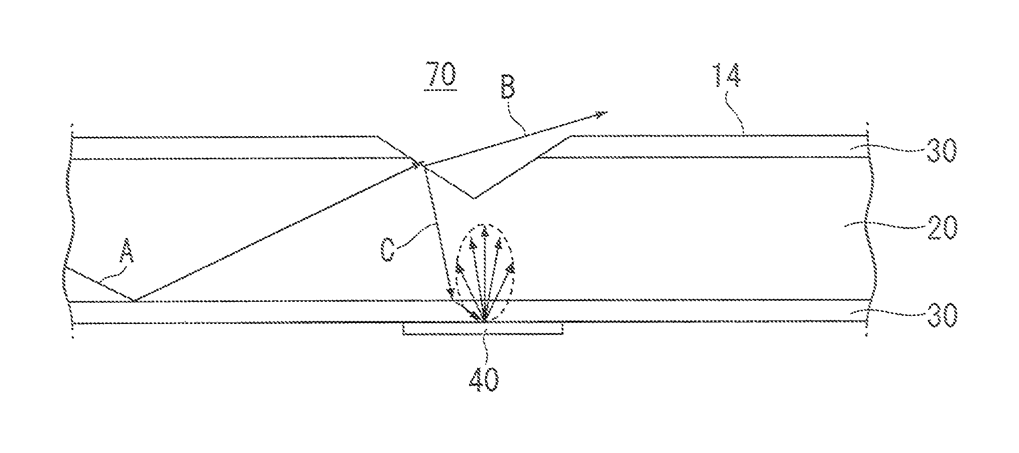
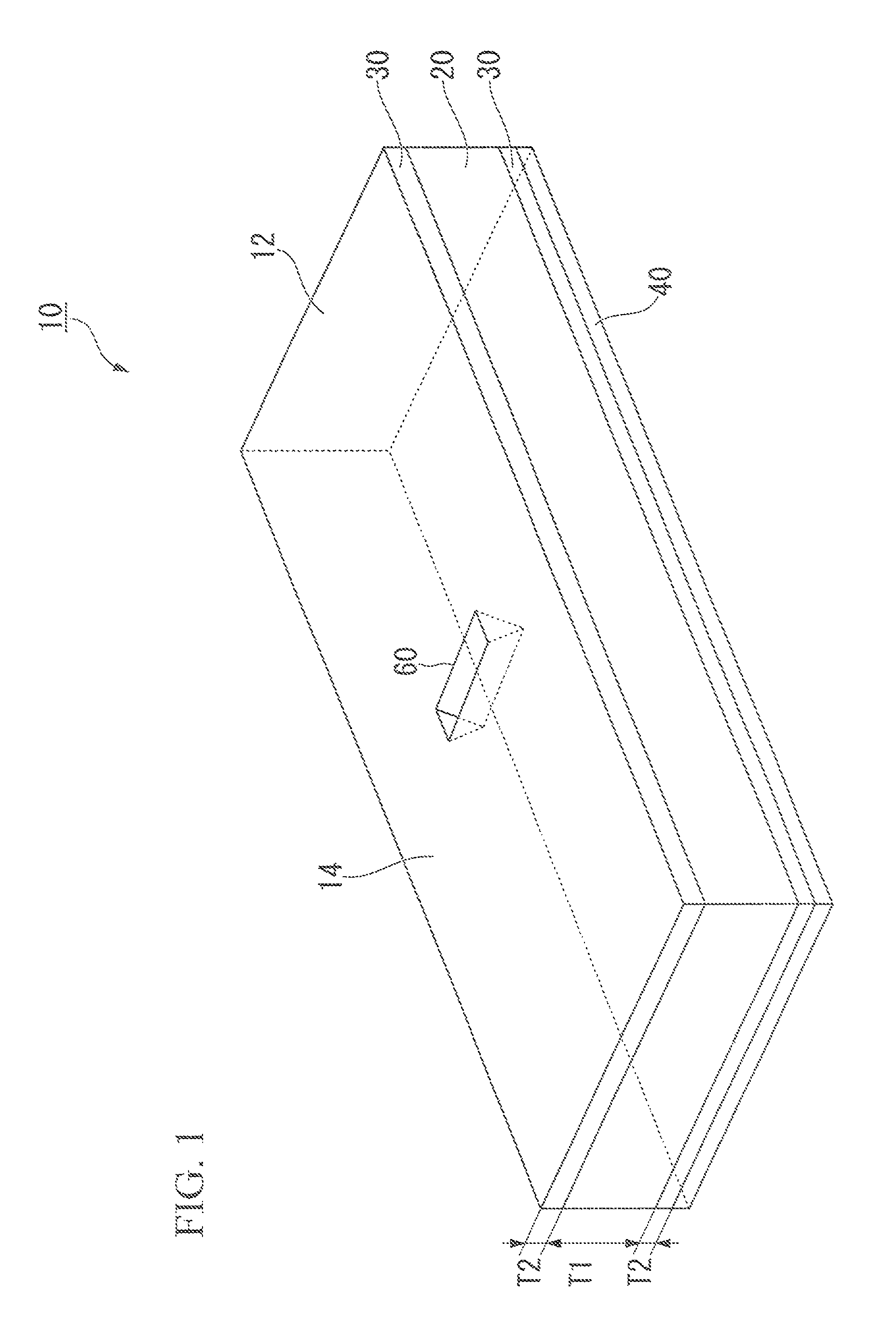
[0042]A light guide for a light source device according to a first embodiment of the invention will be described using FIG. 1. FIG. 1 is a perspective diagram of a light guide 10 for a light source device according to the first embodiment. As shown in FIG. 1, the light guide 10 for a light source device has a core layer 20 and cladding layers 30 which are provided on both surfaces of an upper surface and a lower surface which are the main surfaces of the core layer 20, and a light reflection layer 40 is provided in the front surface of one cladding layer 30, the front surface of the other cladding layer 30 is set as a light emitting face 14, and a recess is provided in the light emitting face as a light emitting means. Then, one side surface of the light guide 10 for a light source device is set as a light incidence face 12. Here, the shape of the light guide 10 for a light source device is not particularly limited as long as it is a plate shape and may be a multi-angular shape, suc...
second embodiment
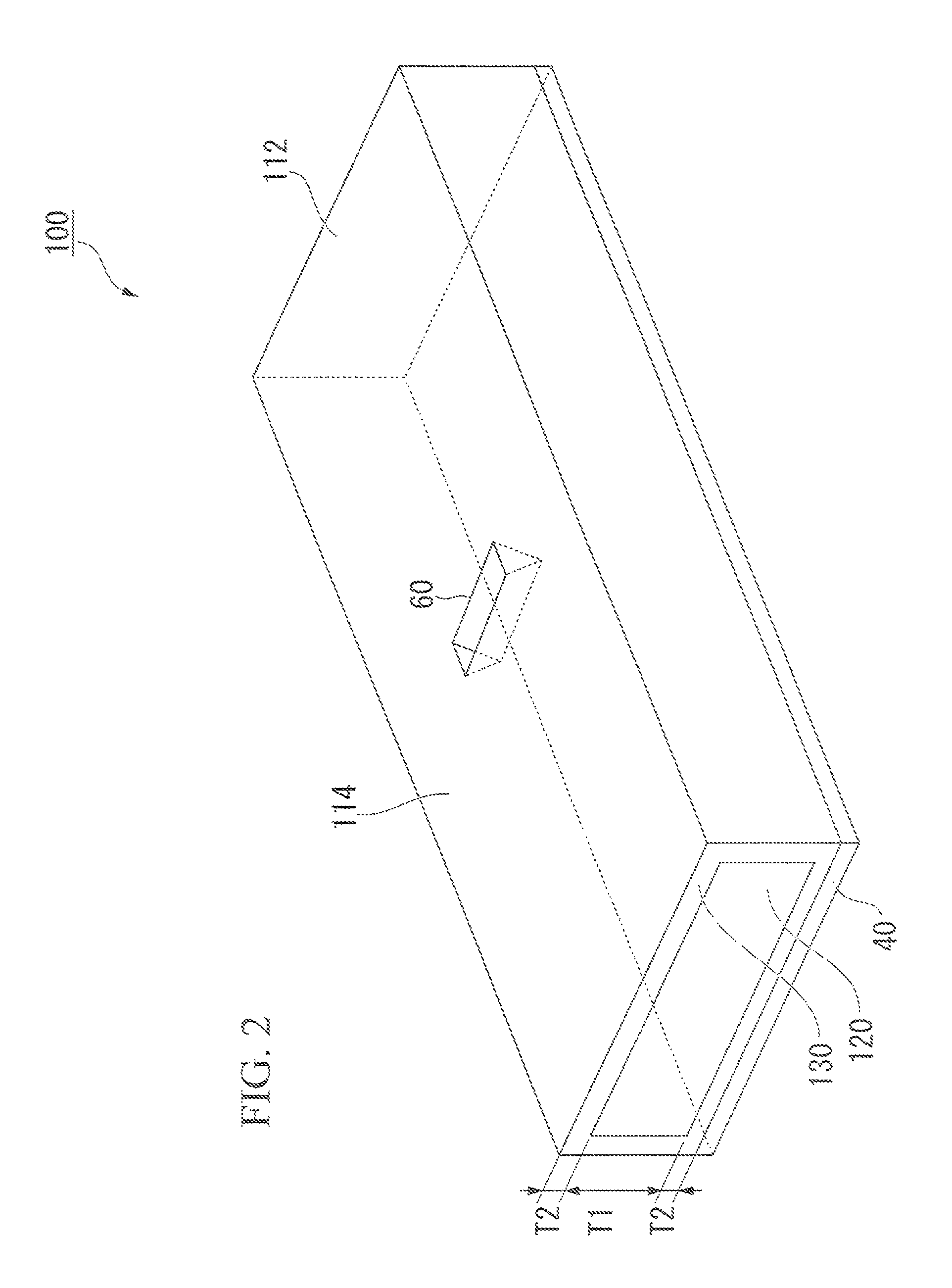
[0085]A light guide for a light source device according to a second embodiment of the invention will be described using FIG. 2. FIG. 2 is a perspective diagram of a light guide 100 for a light source device according to the second embodiment. As shown in FIG. 2, the light guide 100 for a light source device has a core layer 120, cladding layers 130 which are provided so as to cover both surfaces of an upper surface and a lower surface which are the main surfaces of the core layer 120 and two side surfaces which face toward the opposite surface from a light emitting face 114, and the light reflection layer 40 which is provided on the front surface of the cladding layer 130 on the opposite side to the light emitting face 114, and the light guide 100 for a light source device is the same as the first embodiment other than that one of the side surfaces where the cladding layer 130 is not provided is set as a light incidence face 112.
[0086]The material of the core layer 120 is the same a...
third embodiment
[0093]An example of a third embodiment of the invention will be described using FIG. 7. FIG. 7 is a partial cross-sectional diagram of a light guide 210 according to a third embodiment of the invention. As in FIG. 7, the light guide 210 is provided with a rear-surface-side light scattering section 230 which is formed on a rear surface of the opposite side to a light emitting face of the light guide 210 for a light source device with a plate shape, which has a core layer 264 and cladding layers (224, 262) which are provided on both surfaces of an upper surface and a lower surface which are the main surfaces of the core layer 264, by a second light reflecting layer being provided in an inner portion of a recess which passes through the rear-surface-side cladding layer 224 and reaches the core layer 264. Here, the portions where there is no particular description are the same as those of the first embodiment.
[0094]Light Guide for Light Source Device
[0095]In the light guide 220 for a li...
PUM
 Abstract
Description
Claims
Application Information
 - R&D
- Intellectual Property
- Life Sciences
- Materials
- Tech Scout
- Unparalleled Data Quality
- Higher Quality Content
- 60% Fewer Hallucinations
Browse by: Latest US Patents, China's latest patents, Technical Efficacy Thesaurus, Application Domain, Technology Topic, Popular Technical Reports.
© 2025 PatSnap. All rights reserved.Legal|Privacy policy|Modern Slavery Act Transparency Statement|Sitemap|About US| Contact US: help@patsnap.com