
System and method for integrally forming a stiffener with a fiber metal laminate

a technology of fiber metal laminate and stiffener, which is applied in the direction of valves, soldering devices, welding devices, etc., can solve the problems of increasing operating and maintenance costs, increasing the number of fasteners, and time-consuming and laborious processes, so as to reduce stress concentrations in the skin, prolong the service life of the structural assembly, and improve the effect of strength and weigh

Active Publication Date: 2014-03-25
THE BOEING CO
View PDF15 Cites 7 Cited by
  • Summary
  • Abstract
  • Description
  • Claims
  • Application Information

AI Technical Summary

Benefits of technology

This approach eliminates the need for mechanical fasteners, reduces fabrication and assembly time and costs, enhances the strength and weight efficiency of the structure, and extends the service life by minimizing stress concentrations and improving impact resistance and fatigue life compared to conventional methods.

Problems solved by technology

For large aircraft, thousands of such fastener holes must typically be drilled and an equal number of fasteners must be installed in a time-consuming and labor-intensive process in order to attach the stiffeners to the skin.
Although mechanical fastening of stiffeners to skins has been a satisfactory method for its intended purpose, such method presents certain drawbacks which, over time, can increase operating and maintenance costs and can reduce service life.
Particularly in primary load-carrying members of an aircraft such as the aircraft fuselage, skins are subjected to repeated applications of high operating loads which, in turn, results in the repeated concentration of localized stresses at the fastener holes.
Over time, such localized stress concentrations may lead to the occurrence of undesirable effects in the skin.
Although fiber metal laminate skins tend to limit the manifestation of such undesirable effects as compared to homogeneous metallic skins, such undesirable effects may nonetheless occur.

Method used


Image

  • System and method for integrally forming a stiffener with a fiber metal laminate
  • System and method for integrally forming a stiffener with a fiber metal laminate
  • System and method for integrally forming a stiffener with a fiber metal laminate

Examples


Embodiment Construction

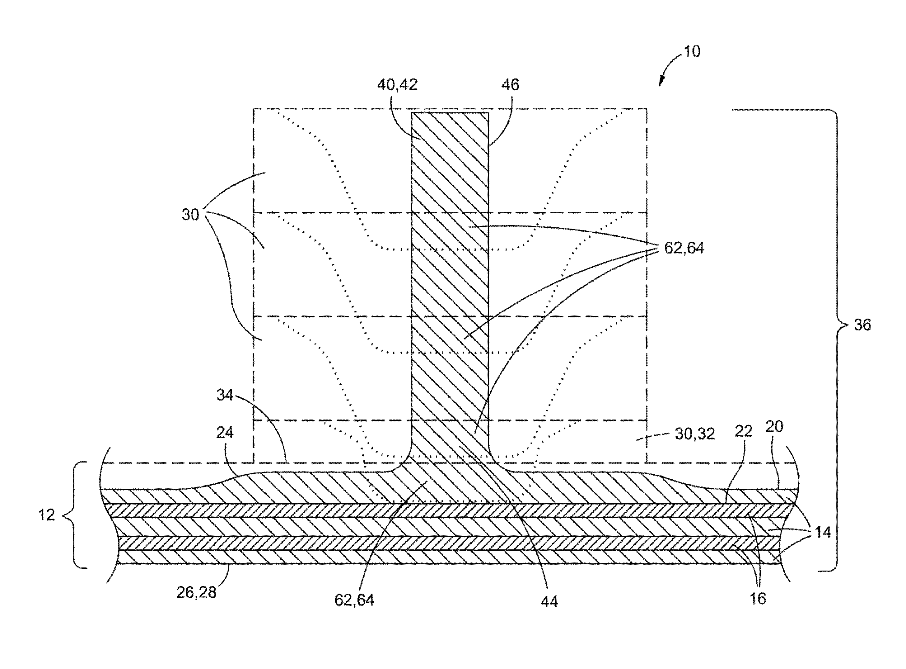
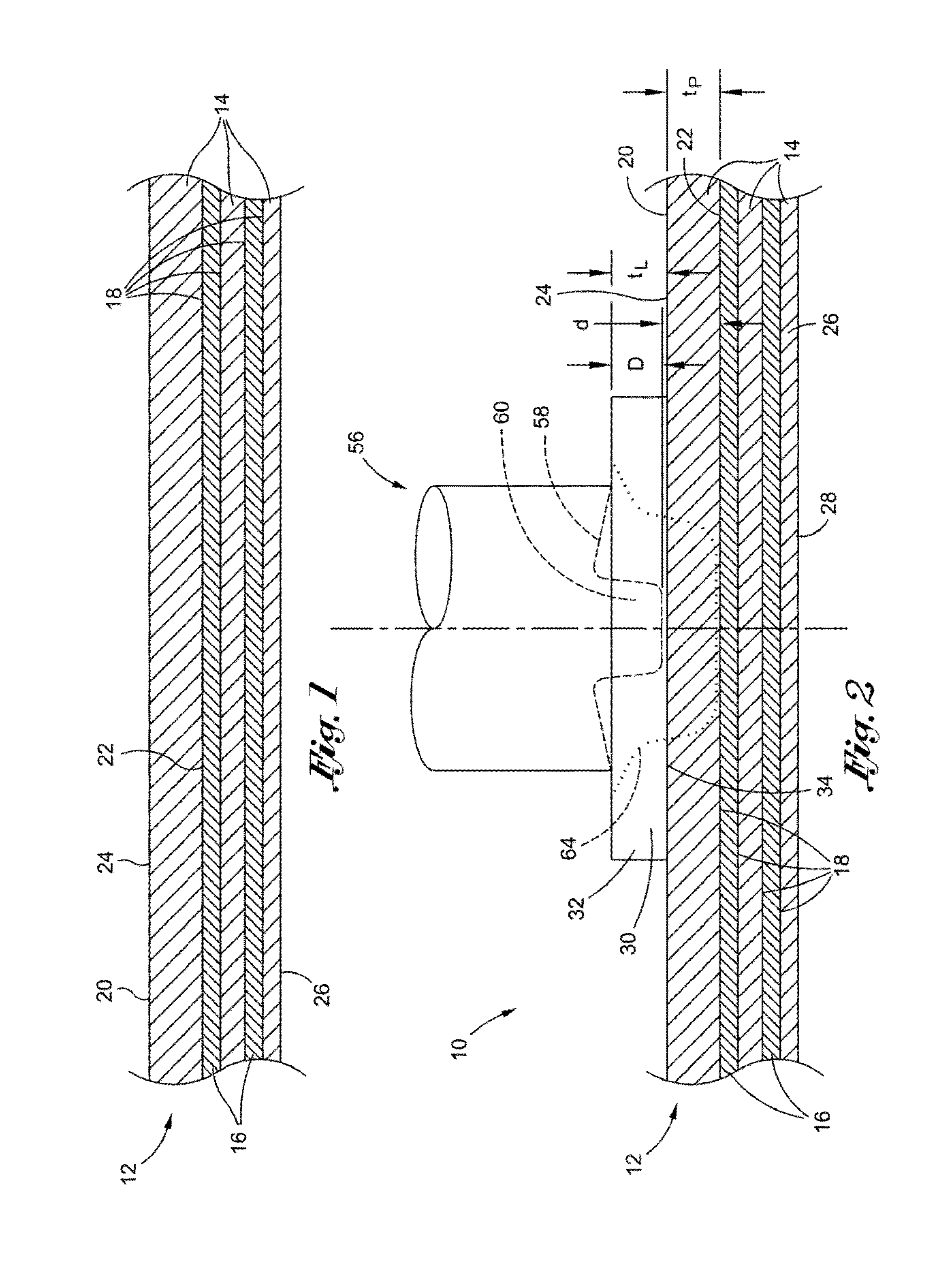
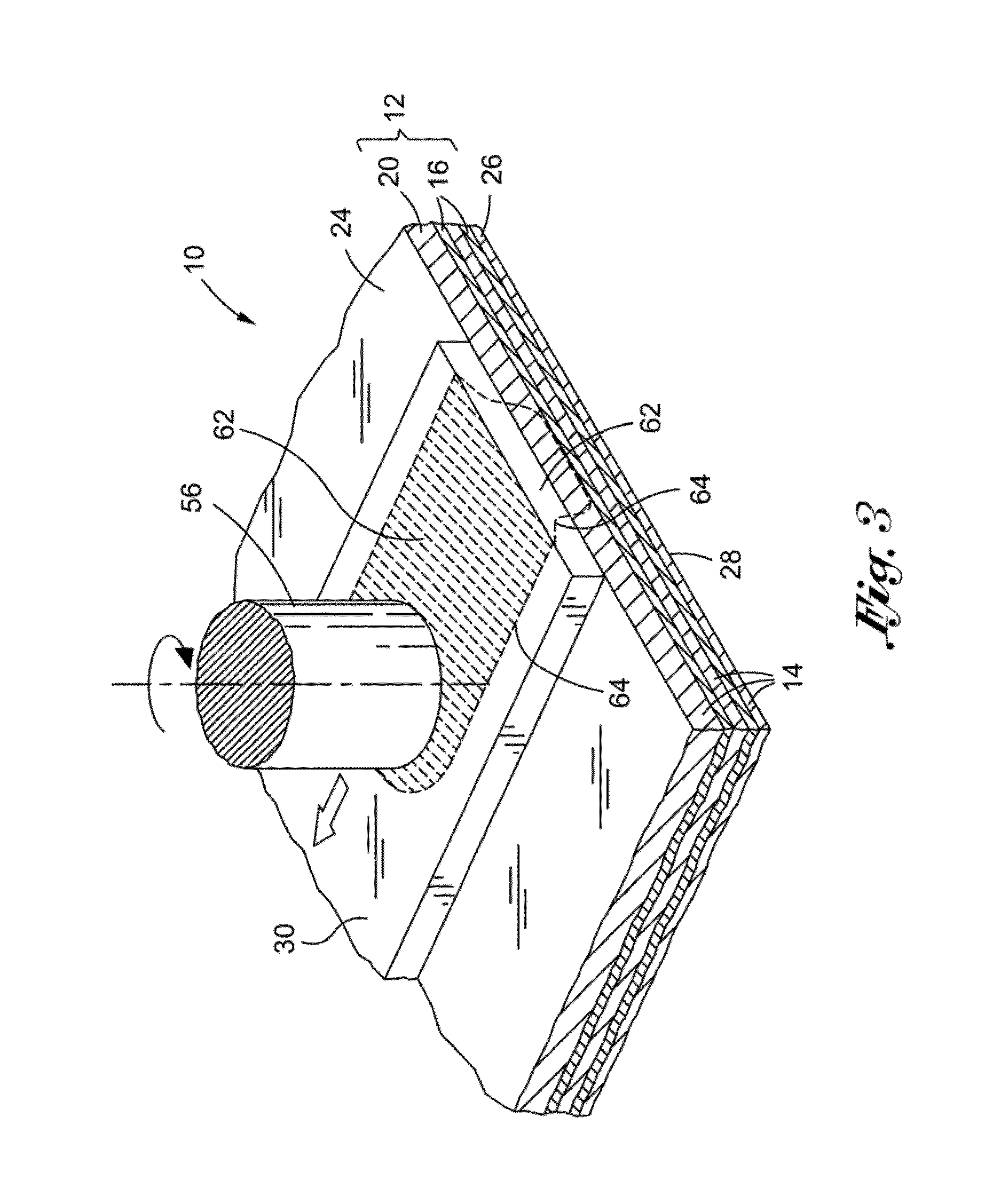
[0048]Referring now to the drawings wherein the showings are for purposes of illustrating preferred and various embodiments of the disclosure only and not for purposes of limiting the same, shown in FIGS. 1-20 is a system and method for fabricating a unitized assembly 10 comprising a fiber metal laminate 12 and an integrally formed substructure element 40. In one embodiment, the unitized assembly 10 may be fabricated by depositing at least one or, more preferably, a plurality of additive layers 30 such as metallic strips onto the fiber metal laminate 12.

[0049]In the embodiments illustrated in FIGS. 1-13, the additive layers 30 may be deposited onto the fiber metal laminate 12 using friction stir welding to create a friction stir welded preform 36. Substructure elements 40 such as stiffeners 42 may be machined into the friction stir welded preform 36 to create the unitized assembly 10. In an alternative embodiment illustrated in FIGS. 14-17, a stock member 70 such as a metal plate ma...


PUM

PropertyMeasurementUnit
thicknessaaaaaaaaaa
thicknessaaaaaaaaaa
thicknessaaaaaaaaaa

Abstract

A unitized assembly comprises a fiber metal laminate having at least one additive layer deposited thereonto such as by friction stir welding. The fiber metal laminate comprises metallic and non-metallic plies and having an innermost metallic ply. The innermost metallic ply and the additive layer are each sized and configured to facilitate the generation of thermal energy sufficient to deposit the first additive layer to the innermost metallic ply during the friction stir welding process. The additive layer is sized and configured to minimize thermal loads in the innermost metallic ply during deposition thereof. The unitized assembly may be formed using a stock member such as a metallic plate from which the innermost metallic ply may be machined. The metallic and non-metallic plies may be laid up over the innermost metallic ply. The substructure elements may be machined from the metallic plate.

Description

CROSS-REFERENCE TO RELATED APPLICATIONS[0001](Not Applicable)STATEMENT RE: FEDERALLY SPONSORED RESEARCH / DEVELOPMENT[0002](Not Applicable)FIELD[0003]The present disclosure relates generally to fiber metal laminate structures and, more particularly, to a system and method for forming unitized fiber metal laminate skins with integral substructure elements such as stiffeners.BACKGROUND[0004]Many airframe structural assemblies such as an aircraft fuselage are commonly-fabricated using a technique known as semi-monocoque construction. In this construction technique, high strength materials such as aluminum alloys are used to form an outer skin. Various substructure elements such as stiffeners are attached to the outer skin. The outer skin is typically designed to carry tension loads while the stiffeners are typically designed to carry bending and compression loads. The combination of the outer skin and the attached stiffeners results in a high-strength, low-weight structure that is well-s...

Claims


Application Information

Patent Timeline
Patent Type & Authority Patents(United States)
IPC IPC(8): B23K20/12
CPCB23K20/12B64C1/12B32B15/14B64C2001/0072B29C65/06B23K2201/001Y10T428/12347Y10T428/12375Y10T428/1241Y10T428/12444Y10T428/31678B32B5/22B32B5/26B32B7/12B32B15/043B32B15/20B32B3/08B32B3/30B32B2262/101B32B2262/106B32B2307/30B32B2307/50B32B2307/558B32B2307/718B32B2605/00B23K2101/001
Inventor HECK, DAVID P.STRAHM, LOREN J.
Owner THE BOEING CO
Learn More