Structures utilizing phase change for heat management applications

a technology of phase change and structure, applied in the field of ceramic materials, can solve the problems of system at the upper limit of performance and the capability of its constituent materials, unsatisfactory limits on design and/or duty cycles, and significant weight and complexity penalties

Active Publication Date: 2014-03-25
LOCKHEED MARTIN CORP
View PDF11 Cites 3 Cited by
  • Summary
  • Abstract
  • Description
  • Claims
  • Application Information

AI Technical Summary

Problems solved by technology

Extreme environments such as those found in solid rocket motor (SRM) boost propulsion nozzles, hypersonic and control surfaces are demanding on the structural materials used in them.
Carbon based composites are frequently used for such applications but suffer from significant erosion and recession through their service life, thus imposing undesirable limits on design and / or duty cycles.
However, these systems are at the upper limits of performance and the capability of their constituent materials.
However, solid rocket motors and reentry vehicles typically do not have such systems and their addition would come with significant penalties in weight and complexity.

Method used


Image

  • Structures utilizing phase change for heat management applications
  • Structures utilizing phase change for heat management applications

Examples


example

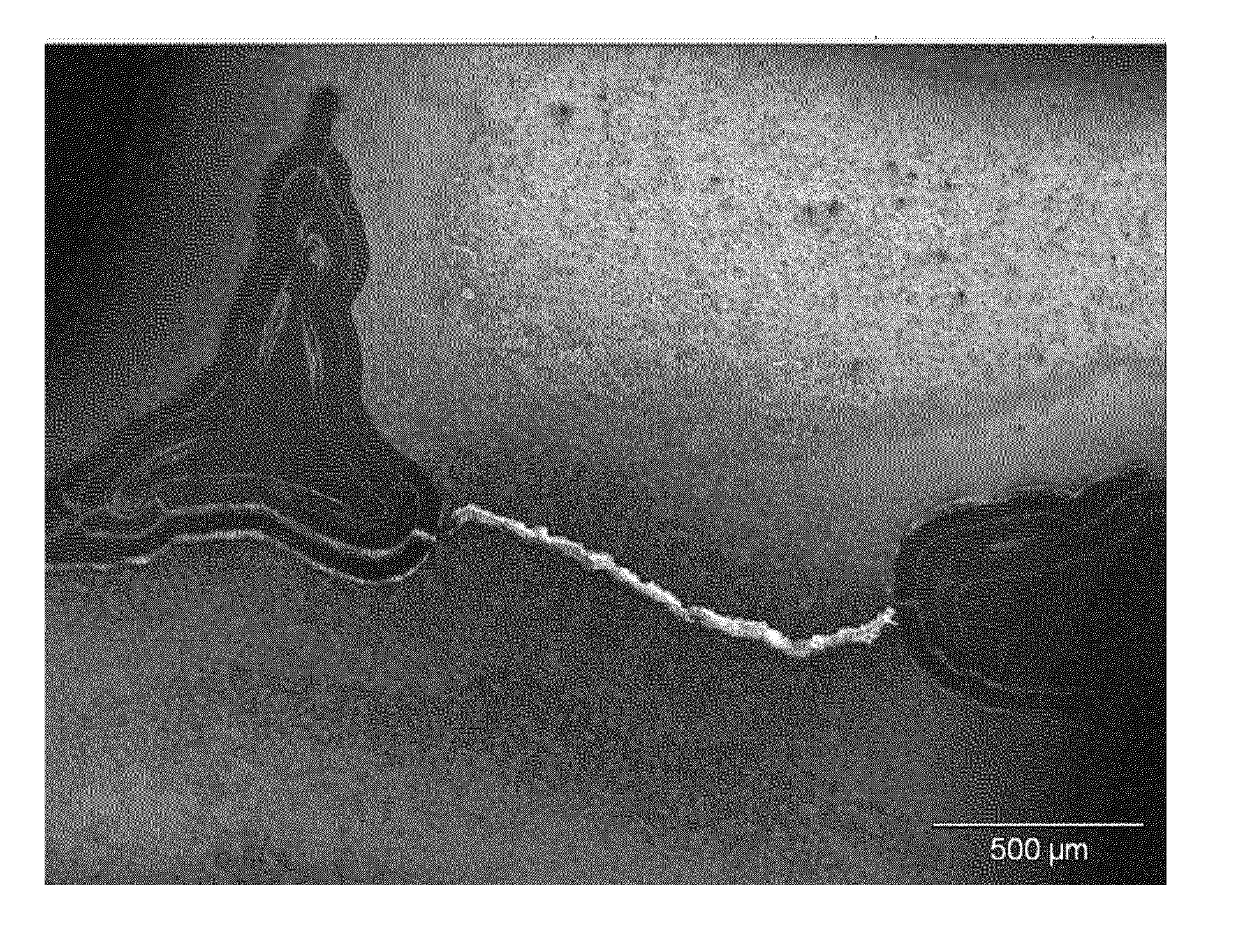
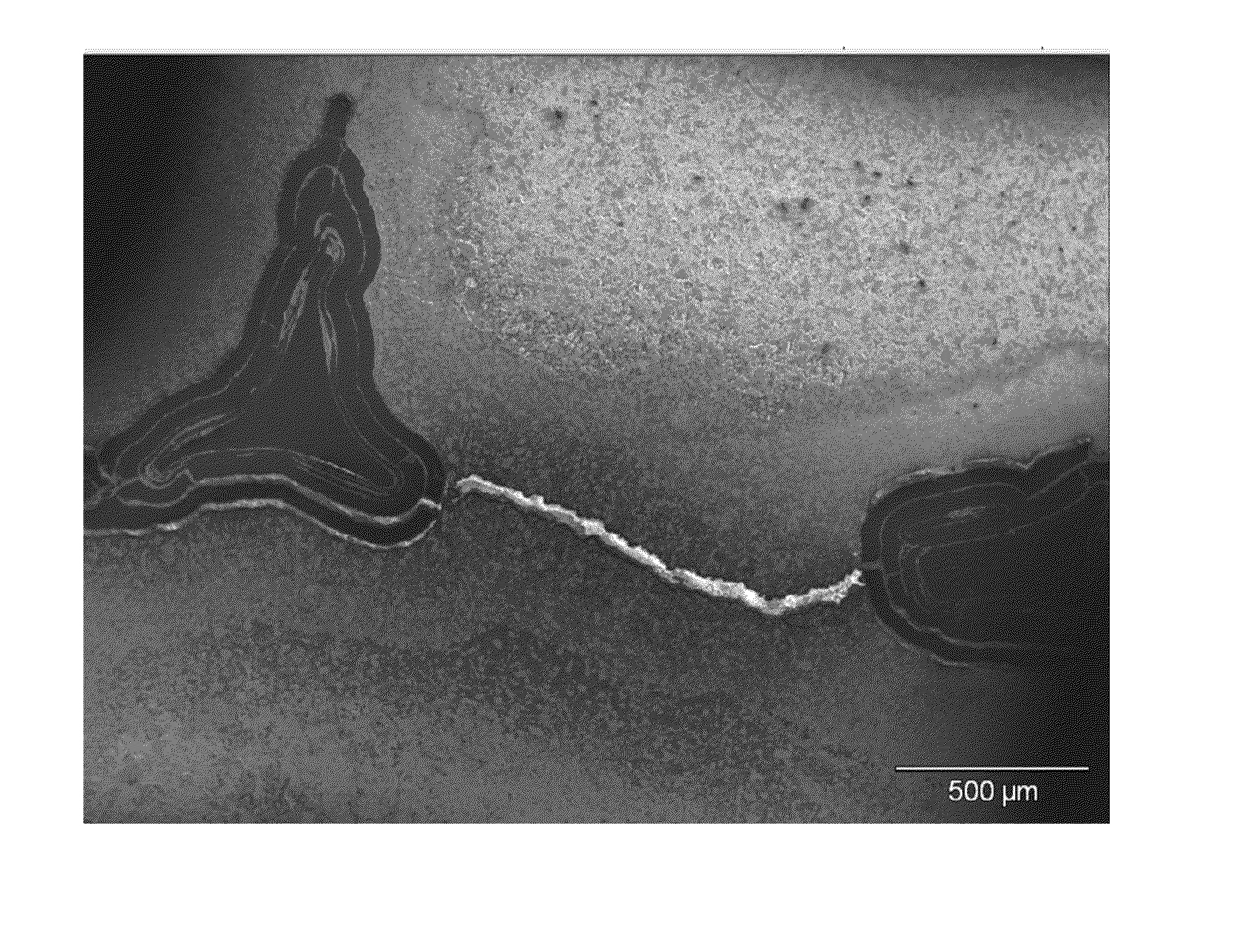
[0026]A sample of an open-cell reticulated B4C ceramic foam, having a density of about 10% and a porosity of about 5-10 ppi, is loaded into a graphite or refractory metal die, and a blend of TaC and Ta2C powder having a 325 mesh particle size is poured into the die on top of the ceramic foam, with vibration used to enhance penetration of the powder into the foam. After the foam has been fully penetrated with the powder, it is subjected to hot isostatic pressing at a pressure of about 1000 psi and a temperature of about 1650° to form a sintered monolithic article. The article is removed from the press and allowed to cool before being subjected to thermal testing. A photomicrograph of a cross-section of such an article is shown in FIG. 1, where the dark triangular section is a cross-section of a B4C foam ligament surrounded by the lighter grey section, which is the tantalum-based ceramic matrix material.

[0027]A sample prepared similar to the above description was subjected to simulate...


PUM

PropertyMeasurementUnit
pressureaaaaaaaaaa
temperatureaaaaaaaaaa
pressuresaaaaaaaaaa

Abstract

An article is described that comprises a reticulated foam structure comprising a first ceramic or metal composition, and a second ceramic or metal composition disposed within the reticulated foam structure. The article may be compressed and sintered to form a monolith that can be used for mange heat by consuming heat energy through a phase change of one of the compositions.

Description

CROSS-REFERENCES TO RELATED APPLICATIONS[0001]This patent application claims priority to U.S. Provisional Patent Application Ser. No. 61 / 255,829 filed Oct. 28, 2009, which is incorporated herein by reference in its entirety.BACKGROUND OF THE INVENTION[0002]The present invention generally relates to ceramic materials, more specifically to ceramic materials for use in extreme environments.[0003]Extreme environments such as those found in solid rocket motor (SRM) boost propulsion nozzles, hypersonic and control surfaces are demanding on the structural materials used in them. Carbon based composites are frequently used for such applications but suffer from significant erosion and recession through their service life, thus imposing undesirable limits on design and / or duty cycles. Materials systems that are non-eroding in such environments offer significant improvements in performance and enable more aggressive duty cycles. For example, recent developments have demonstrated near zero eros...

Claims


Application Information

Patent Timeline
Patent Type & Authority Patents(United States)
IPC IPC(8): B32B19/00B32B9/00B32B9/04
CPCF28D15/02C04B38/00C09K5/02C04B35/5607C04B35/6455C04B2235/3821C04B2235/616C04B38/0032C04B38/0058C04B38/0615
Inventor RAMACHANDRAN, GAUTHAMSMITH, SCOTT W.PRASAD, SANJAY
Owner LOCKHEED MARTIN CORP
Why Eureka
Try Eureka