Acoustic touch apparatus

a touch sensor and surface acoustic wave technology, applied in the field of acoustic touch sensors, can solve the problems of observed effects, loss of energy, interference with the propagation of surface acoustic waves on the touch substrate,

Active Publication Date: 2014-03-25
ELO TOUCH SOLUTIONS INC
View PDF9 Cites 46 Cited by
  • Summary
  • Abstract
  • Description
  • Claims
  • Application Information

AI Technical Summary

Benefits of technology

[0009]The above problems are obviated by the present invention which provides an acoustic touch apparatus, comprising a substrate having surfaces capable of propagating surface acoustic waves; at least one acoustic wave transducer on a first surface; and at least one reflective array on the first surface, said transducer capable of transmitting or receiving surface acoustic waves to or from the reflective array and said reflective array capable of acoustically coupling surface acoustic waves to propagate between surfaces of the substrate, and said substrate having a first acoustic element disposed on the first surface that intercepts propagating surface acoustic waves on the first surface and causes variations in the phase velocity of the propagating surface acoustic waves and a second acoustic element disposed on the first surface that equalizes the variations. The second acoustic element may cancel out the phase advance or delay of any portion of the propagating surface acoustic waves intercepted by the first acoustic element. The second acoustic element may be disposed on the first surface in proximity to the first acoustic element or as physically close as possible to the first acoustic element.
[0017]Further, the reflective array may be disposed over the layer of acoustically benign material along the border of the first surface and at least a portion of the cut-out and the patch of the first acoustic element, said propagating surface acoustic waves intercepted by the first acoustic element comprising a portion of the surface acoustic waves interacting with the reflective array, and the second acoustic element may comprise the portion of the reflective array disposed over the cut-out and the patch, said portion having a higher density of reflector elements than the remainder of the reflective array. The higher density may maintain reflector element spacing equal to an integral multiple of the surface acoustic wave wavelength transmitted by the transducer. Alternatively, the higher density may obtain a desired phase velocity of the surface acoustic waves transmitted by the transducer.
[0020]The present invention also provides a method of providing an acoustic touch apparatus with a frit pattern to counteract changes in the phase velocities of propagating surface acoustic waves passing over acoustic material that is disposed on a propagating surface of a substrate of the apparatus and that forms an identification marking, comprising forming the frit pattern with a first segment that leads into one end of the length of the identification marking and a second segment that leads into the opposite end of the length of the identification marking; forming the segments of the frit pattern with graded dimensions that provide a gradated change in the phase velocities of the surface acoustic waves from the surrounding propagating surface to the identification marking; and adjusting the frit pattern, as needed, to accommodate the layout and the particular features on the propagating surface. The method may further comprise forming the frit pattern with at least one third segment that fills in at least one area of the propagating surface surrounding the identification marking. The method may further comprise juxtaposing the segments of the frit pattern and the identification marking in a compact manner.

Problems solved by technology

Touching the substrate surface at a point causes a loss of energy by the surface acoustic waves passing through the point of touch.
In some cases, however, these additional features and functions may interfere with the propagation of surface acoustic waves on the touch substrate.
Generally, it is believed that a surface acoustic wave experiences changes in velocity in passing over the printed material (and thus loses phase coherence) resulting in the observed effects.

Method used


Image

  • Acoustic touch apparatus
  • Acoustic touch apparatus
  • Acoustic touch apparatus

Examples


Embodiment Construction

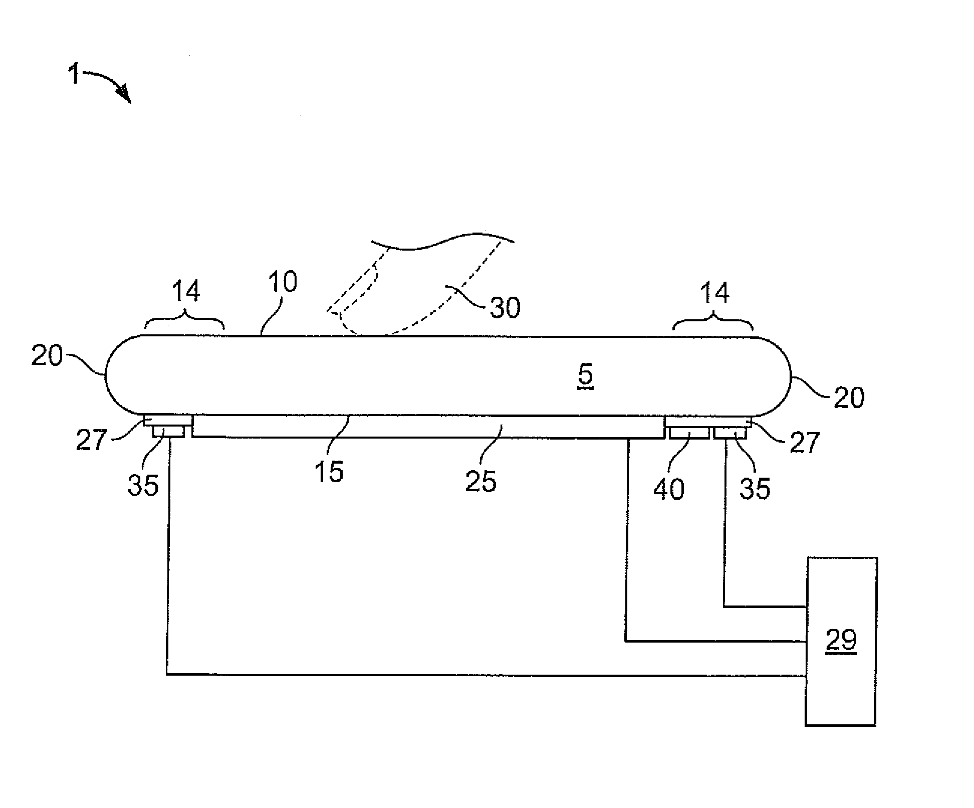
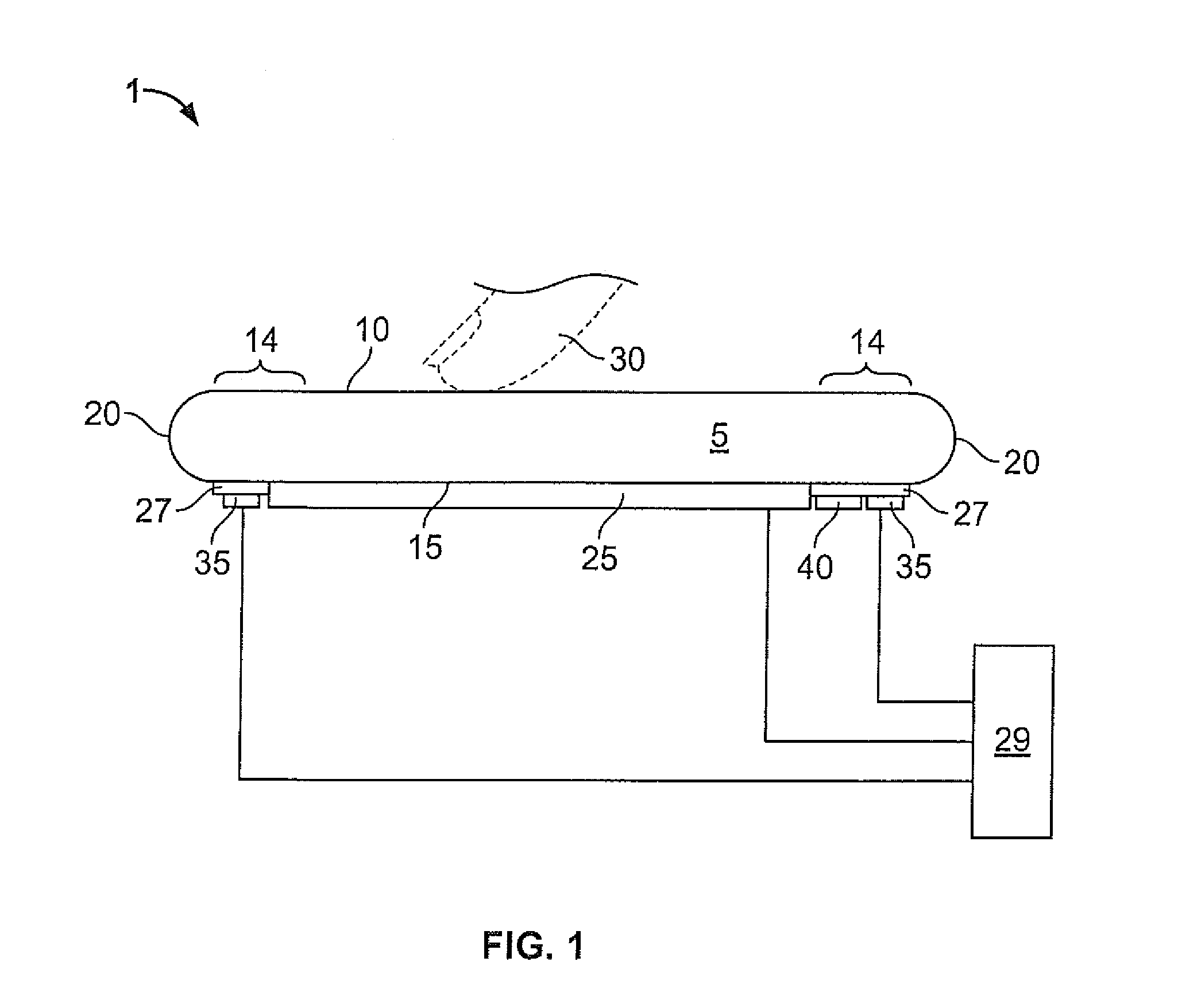
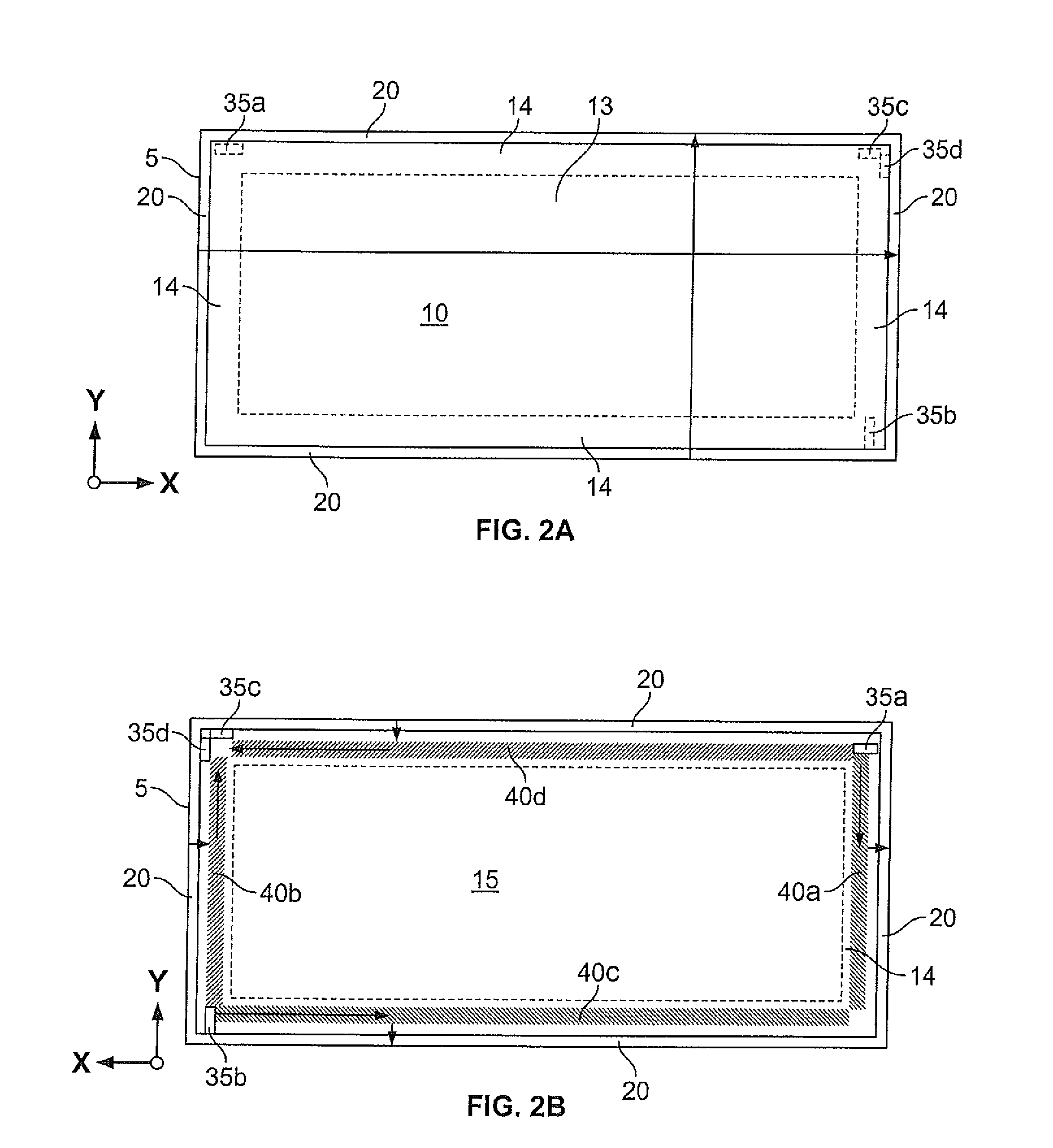
[0049]FIG. 1 shows a simplified cross-sectional view of an acoustic touch sensor 1. The touch sensor 1 comprises a substrate 5 with a front surface 10, a back surface 15, and connecting surfaces 20 joining the peripheral regions 14 of the front surface 10 and of the back surface 15. A connecting surface 20 need not be curved as shown but generally can have any shape that supports transfer of surface acoustic waves between the front and back surfaces 10, 15. The substrate 5 is typically made of some form of glass which overlies a computer display or computing device display 25, like a liquid crystal display (LCD), a cathode ray tube (CRT), plasma, etc. In a bezeled surface acoustic wave touch sensor, the peripheral region 14 of the front surface 10 is covered by a bezel provided by the housing of the touch sensor 1 or the device integrating the sensor 1, since the transducers and reflective arrays are on the front surface 10 of the substrate 5. In a bezel-less surface acoustic wave t...


PUM


Abstract

An improved acoustic touch apparatus that has a logo or application icon applied on the back surface of a propagating substrate which can be viewed through the substrate and an acoustic element situated adjacent the logo or application icon that can compensate for phase velocity shifts of surface acoustic waves in propagating over the logo or application icon.

Description

FIELD OF THE INVENTION[0001]This invention generally relates to acoustic touch sensors and, more particularly, to surface acoustic wave (SAW) touch screens.BACKGROUND OF THE INVENTION[0002]Touch sensor systems, such as touch screens or touch monitors, can act as input devices for interactive computer systems used for various applications, for example, information kiosks, order entry systems, video displays, mobile communications, etc. Such systems may be integrated into a computing device, thus providing interactive touch capable computing devices, including computers, electronic book readers, or mobile communications devices.[0003]Generally, touch sensor systems enable the determination of a position on the surface of a substrate via a user's touch of the surface. The touch substrate is typically made of some form of glass which overlies a computer or computing device display, like a liquid crystal display (LCD), a cathode ray tube (CRT), plasma, etc. The touch sensor system is ope...

Claims


Application Information

Patent Timeline
Patent Type & Authority Patents(United States)
IPC IPC(8): G06F3/043
CPCG06F3/0418G06F3/0436
Inventor SCHARFF, DANIEL H.KENT, JOEL C.
Owner ELO TOUCH SOLUTIONS INC
Why Eureka
Try Eureka