
Suspension system for a vehicle including an electromagnetic actuator

a technology of electromagnetic actuator and suspension system, which is applied in the direction of cycle equipment, instruments, transportation and packaging, etc., can solve the problems that the actuator force generated cannot be transmitted, and the suspension system is complicated, and achieve the effect of preventing the system from being complicated

Inactive Publication Date: 2014-03-25
TOYOTA JIDOSHA KK
View PDF23 Cites 38 Cited by
  • Summary
  • Abstract
  • Description
  • Claims
  • Application Information

AI Technical Summary

Benefits of technology

[0015]Where the “first transfer function” and the “second transfer function” described in the form (1) are utilized, the relationship between the actuator force and the actual acting force can be obtained. In short, where the relationship between the actuator force and the actual acting force is taken into account, the actuator force to be generated by the actuator can be determined such that the actual acting force becomes equal to the required acting force. However, the first transfer function and the second transfer function are set taking account of only the movement of one of the sprung-side unit and the unsprung-side unit relative to one of the sprung portion and the unsprung portion. Actually, the one of the sprung portion and the unsprung portion is being displaced at all times. Accordingly, it is desirable to take account of an influence of the displacement of the one of the sprung portion and the unsprung portion. In view of this, in the form (1), the target actuator force is determined based on the required acting force while utilizing the above-indicated first transfer function and second transfer function, and further based on the inertial force of the one of the sprung-side unit and the unsprung-side unit with respect to the displacement of the one of the sprung portion and the unsprung portion. According to the form (1), therefore, the force that acts between the sprung portion and the unsprung portion can be made appropriate by considering the influence of the displacement of the one of the sprung portion and the unsprung portion, ensuring effective vibration damping. Accordingly, it is possible to prevent deterioration in the riding comfort of the vehicle, the steerability and the stability of the vehicle, and so on, arising from the serial arrangement of the connecting mechanism with respect to the actuator.
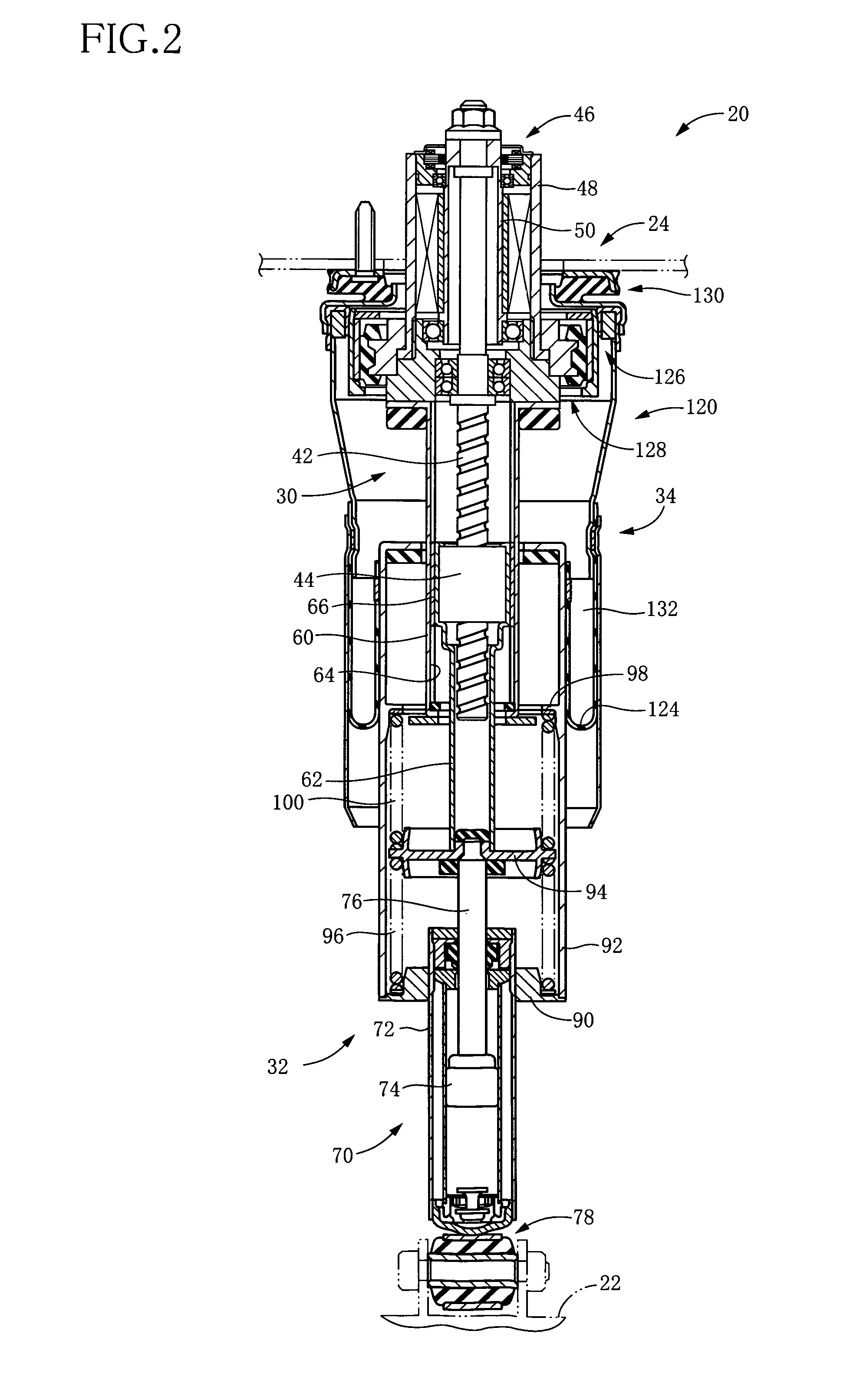
[0030]According to the above form (4), the connecting mechanism is disposed between the unsprung portion and the unsprung-side unit of the actuator, whereby the shock inputted from the wheel and transmitted to the actuator is mitigated and the high-frequency vibration such as unsprung resonance is dealt with. According to the form (4), therefore, the shock transmitted to the electromagnetic motor and the high-frequency vibration can be effectively suppressed, so that the suspension system with high reliability is realized.
[0034]In the above two forms (5) and (6), there is employed a connecting mechanism in which the hydraulic damper is disposed in parallel to the support spring. The “damper” may be provided for assisting the support spring, namely, for damping the vibration having a relatively high frequency. According to the above two forms, therefore, it is possible to effectively damp the high-frequency vibration such as unsprung resonance. While the structure of the damper is not particularly limited, the damper may have a structure as a cylinder device having a housing, a piston, and so on. Where the connecting mechanism includes the damper, the first transfer function and the second transfer function are set using the damping coefficient of the damper as described in the latter form (6).
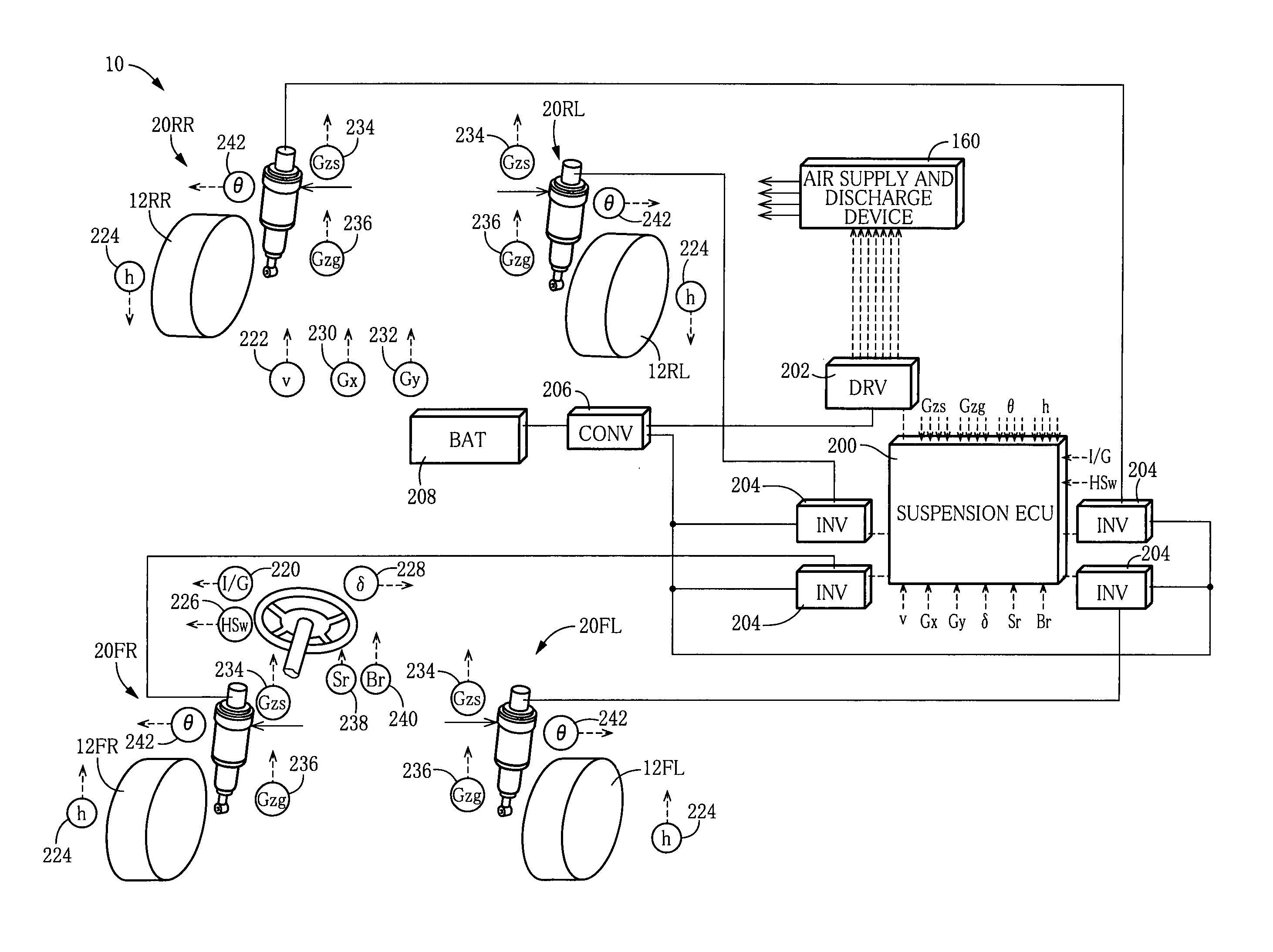
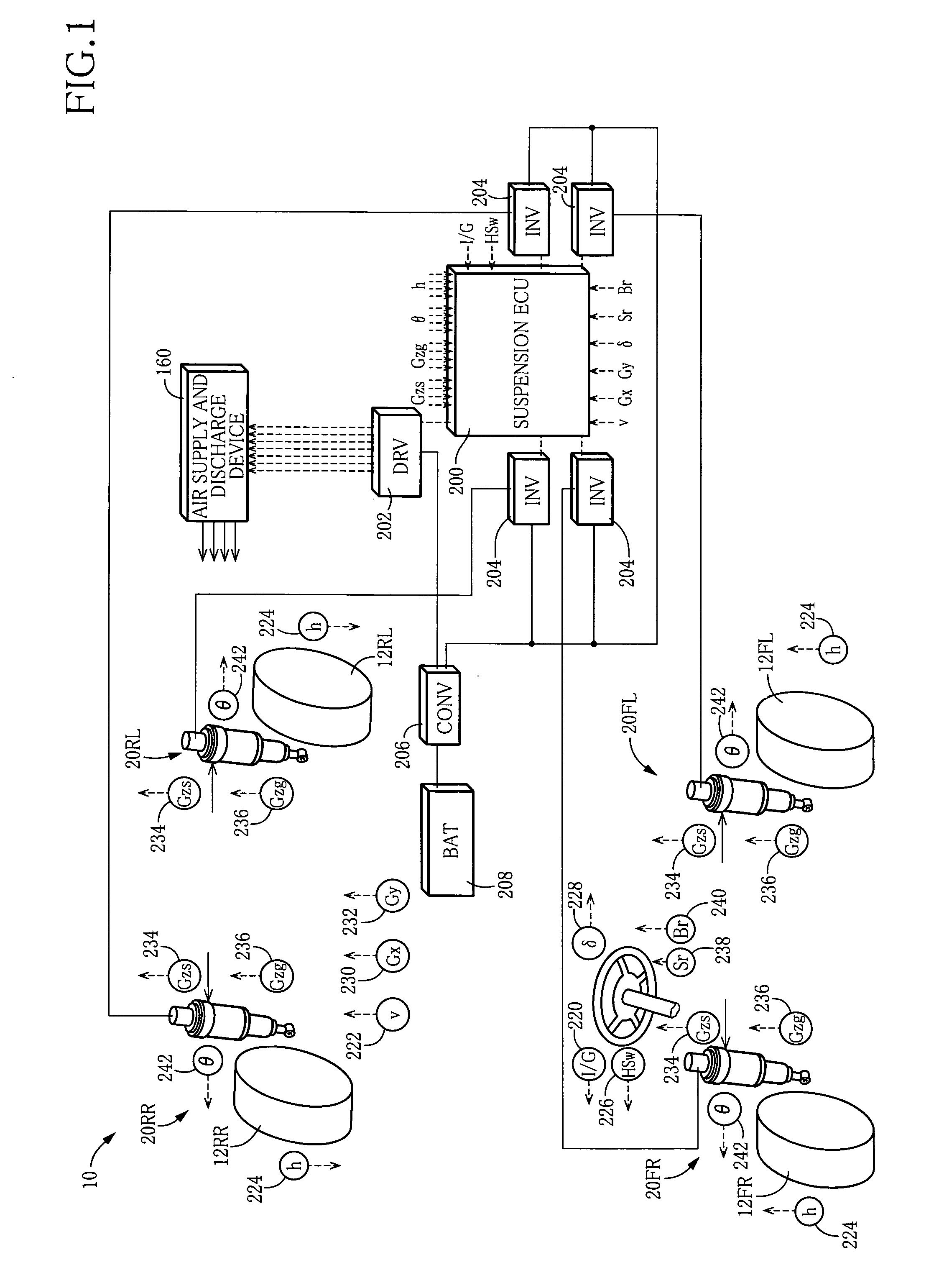
[0041]In the above form (8), the technique of estimating the direction of the relative movement of the one of the sprung-side unit and the unsprung-side unit and the one of the sprung portion and the unsprung portion is embodied. The actuator is constructed such that the relative movement of the sprung-side unit and the unsprung-side unit and the operation of the motor are interrelated. Accordingly, the amount of the relative movement of the sprung-side unit and the unsprung-side unit (hereinafter referred to as “unit-relative-movement amount” where appropriate) can be estimated from the detected value of the motor-operation-amount sensor. Therefore, the direction of extension and contraction of the damper can be estimated from a change in the difference between the amount of the movement of the sprung portion and the unsprung portion toward and away from each other detected by the movement-amount sensor and the unit-relative-movement amount estimated from the detected value of the motor-operation-amount sensor. Because the movement-amount sensor and the motor-operation-amount sensor are those required in the ordinary control of the actuator and the like executed by the suspension system, the form (8) eliminates provision of additional sensors, preventing the system from being complicated.

Problems solved by technology

Accordingly, the suspension system suffers from a problem that the actuator force as generated cannot be transmitted due to a time lag that arises from transmission of the actuator force via the spring, and the like.

Method used


Image

  • Suspension system for a vehicle including an electromagnetic actuator
  • Suspension system for a vehicle including an electromagnetic actuator
  • Suspension system for a vehicle including an electromagnetic actuator

Examples


modified embodiment

[0083]In the system according to the illustrated embodiment, the target-actuator-force determining portion is configured such that the required acting force is inputted into the composite transfer function G(s) set as the reciprocal function of the function that is a product of the first transfer function and the second transfer function, as shown in FIG. 7(a). The target-actuator-force determining portion may be configured such that the target actuator force is calculated using a composite transfer function H(s) shown in FIG. 7(b). The composite transfer function H(s) is a transfer function that is approximate to the transfer function G(s) in the illustrated embodiment and is represented as follows:

H(s)=G′(s) / {1+G′(s)·A(s)}

In the above formula, “G′(s)” and “A(s)” are transfer functions represented by the following formulas, respectively:

G′(s)=P+I / s+D·s

A(s)=(C·s+k) / (m·s2+C·s+k)

In the above formulas, “P”, “I”, and “D” are a proportional gain, an integral gain, and a differential gai...


PUM


Abstract

A suspension system for a vehicle, including: an electromagnetic actuator configured to generate an actuator force and including a sprung-side unit connected to a sprung portion, an unsprung-side unit connected to an unsprung portion, and an electromagnetic motor; a connecting mechanism; and a controller including a target-actuator-force determining portion, the determining portion being configured to determine a target actuator force based on: (a) a required acting force that is a force required to act between the sprung and unsprung portions; and (b) an inertial force of one of the sprung-side and unsprung-side units, while utilizing: a first transfer function by which is outputted an amount of a displacement of the one of the sprung-side and unsprung-side units when the actuator force is inputted; and a second transfer function by which is outputted an actual acting force which actually acts between the sprung and unsprung portions when the displacement amount is inputted.

Description

TECHNICAL FIELD[0001]The present invention relates to a suspension system including an electromagnetic actuator.BACKGROUND ART[0002]In recent years, there has been developed, as a suspension system for a vehicle, the so-called electromagnetic suspension system including an electromagnetic actuator configured to generate, with respect to a sprung portion and an unsprung portion, a force in a direction in which the sprung portion and the unsprung portion are moved toward and away from each other, based on a force of an electromagnetic motor. For instance, the following Patent Document 1 discloses such an electromagnetic suspension system. The disclosed suspension system is expected as a high-performance suspension system in view of an advantage that it is possible to easily realize a vibration damping characteristic based on the so-called skyhook theory because the suspension system can generate a propulsive force with respect to a relative movement of the sprung portion and the unspr...

Claims


Application Information

Patent Timeline
Patent Type & Authority Patents(United States)
IPC IPC(8): B60G17/018B60G11/00B60G17/019B60G13/00B60G17/015
CPCB60G2400/104B60G2400/252B60G2400/41B60G2202/25B60G2202/42B60G13/16B60G2202/32B60G17/018B60G2400/204B60G2400/33B60G2400/102B60G17/0157B60G2202/44B60G2400/106
Inventor NAKAMURA, TOMOMICHI
Owner TOYOTA JIDOSHA KK
Learn More