Durable connector for base unit handle of a patient head support system

a technology for supporting systems and patients, applied in the field of patient head support systems, can solve the problems of permanent distortion of the bore, no longer fitting the post in the bore, damage to the base unit handle, etc., and achieve the effects of relaxing the tolerances of the structure, avoiding damage, and protecting the delicate surface of the bore from distortion and abrasion

Active Publication Date: 2014-04-01
INTEGRA LIFESCI
View PDF18 Cites 5 Cited by
  • Summary
  • Abstract
  • Description
  • Claims
  • Application Information

AI Technical Summary

Benefits of technology

[0017]The present invention achieves these objects by retaining a sleeve, or bushing, within the bore of a base unit handle, the sleeve having an external surface that cooperates with the interior surface of the bore, and an internal surface that cooperates with a post, or shaft, of an intervening member. The sleeve supplies resistance to the closing force of the lever of the base unit handle. Because the sleeve remains in the bore, this structure eliminates problems related to the inadvertent closing of the lever when the bore is empty. More specifically, this structure eliminates the damage that would otherwise be caused to the bore of the base unit handle upon inadvertent closing of the lever. It also enables a relaxing of the tolerances of the structures used to hold the intervening member to the base unit handle.
[0018]Essentially, the sleeve serves as a connector between the base unit and the intervening member, such as an adaptor or a transition member, which in turn supports the skull clamp or headrest. When retained in place as part of a base unit handle, the sleeve protects the delicate surfaces of the bore from distortion and abrasion that could result from careless treatment.
[0019]According to one aspect of this invention, the sleeve and intervening member provide the connection security of a positive clutch, combined with the infinite positioning of a lockable sliding joint. More specifically, the sleeve or bushing carries a pair of clutch mechanisms, such as ratchet teeth or starburst connectors, at each of its opposite ends. These ratchet teeth are operable to selectively engage a complementary starburst on a protrusion of the intervening member, typically a transition member. These connectors enable the sleeve to be independently secured to the transition member. This can occur, for instance, by threadably securing the post of the transition member into the sleeve, via external threads on the post that complement internal threads of the sleeve. This combination of a threaded connector and the opposed starburst connection allows the transition member and sleeve to be independently connected, so as to be rotatable relative to the bore when the lever is open. But when the lever moves from an unlocked to the locked position, the sleeve and the transition member become fixed in position relative to the bore.
[0020]The sleeve's circumferential external surface mimics the outer cylindrical surface of a conventional transition member, so that it will rotate freely in the bore when the lever is open, or unlocked, and be gripped tightly when the lever is closed, or locked. This structure allows non-incremental rotation of the sleeve and the transition member within the bore. The sleeve is sized and / or shaped so as to provide some resistance to contraction of the bore during closing of the lever. The sleeve can be made of any resilient metal, for example, stainless steel, aluminum or titanium, or any other suitable material, including a radiolucent material, if radiolucency is desired. The starburst connectors add to the versatility of this structure. That is, this structure combines non-incremental rotation relative to the base unit handle with the rigidity of a clutch-type connection between the base unit handle and the intervening member, via the starburst connectors. The cooperating ratchets prevent rotation between the transitional member and the sleeve so that they move (or are immobilized) as a single unit when they are fastened together.
[0021]Also, the sleeve includes a central circumferential groove in its outer surface. This helps to prevent the sleeve from binding rotationally if the cam rod deforms the casting.
[0022]In summary, the present invention eliminates the potential for damaging the portion of the base unit handle that defines the bore. This invention achieves consistency and repeatability in achieving an immobilizing force between a base unit handle and an intervening member. Moreover, this invention achieves a robust connection of head supporting components without sacrificing any flexibility. Also, the centrally located groove of the sleeve can, to some extent, accommodate any central bulging of material into the bore that might be caused by the cam rod, if the operator does not actively control movement of the lever.

Problems solved by technology

Also, the base unit handle can be damaged by the inadvertent moving of the locking lever into the closed position when the bore is empty.
This can cause permanent distortion of the bore due to the compound leverage achieved via the closed lever.
Once the bore has been bent out of shape, it is highly possible that the post will no longer fit in the bore, at least not with the proper frictional fit.
Also, when the lever moves from the locked to the unlocked position, it can accelerate rapidly if it is not being actively controlled by the user.
When this occurs, a bulge of material may intrude into the bore, which can make it difficult or impossible to remove the intervening member.
Unfortunately, such warnings are not a failsafe solution to these problems.
In addition to these issues, the outer surface of the cylindrical post of the transition member, when separated from the base unit handle, is susceptible to being marred by careless handling.
In other words, the bore of the base unit handle and the post of the transitional member are in some respects very susceptible to mishandling by surgical attendants, and such mishandling can result in inoperability of the head support system.
To some extent these issues are complicated by the consideration that clinicians will want to be able to connect the intervening member to the base unit on either the right side or on the left side, depending on the circumstances, so that the intervening member can be removed from the base handle unit and switched around to face the other direction, when the opposite orientation is required.
Clinicians are accustomed to this degree of flexibility in the surgical theatre, and any reduction in this capability would not be acceptable.

Method used


Image

  • Durable connector for base unit handle of a patient head support system
  • Durable connector for base unit handle of a patient head support system
  • Durable connector for base unit handle of a patient head support system

Examples


Embodiment Construction

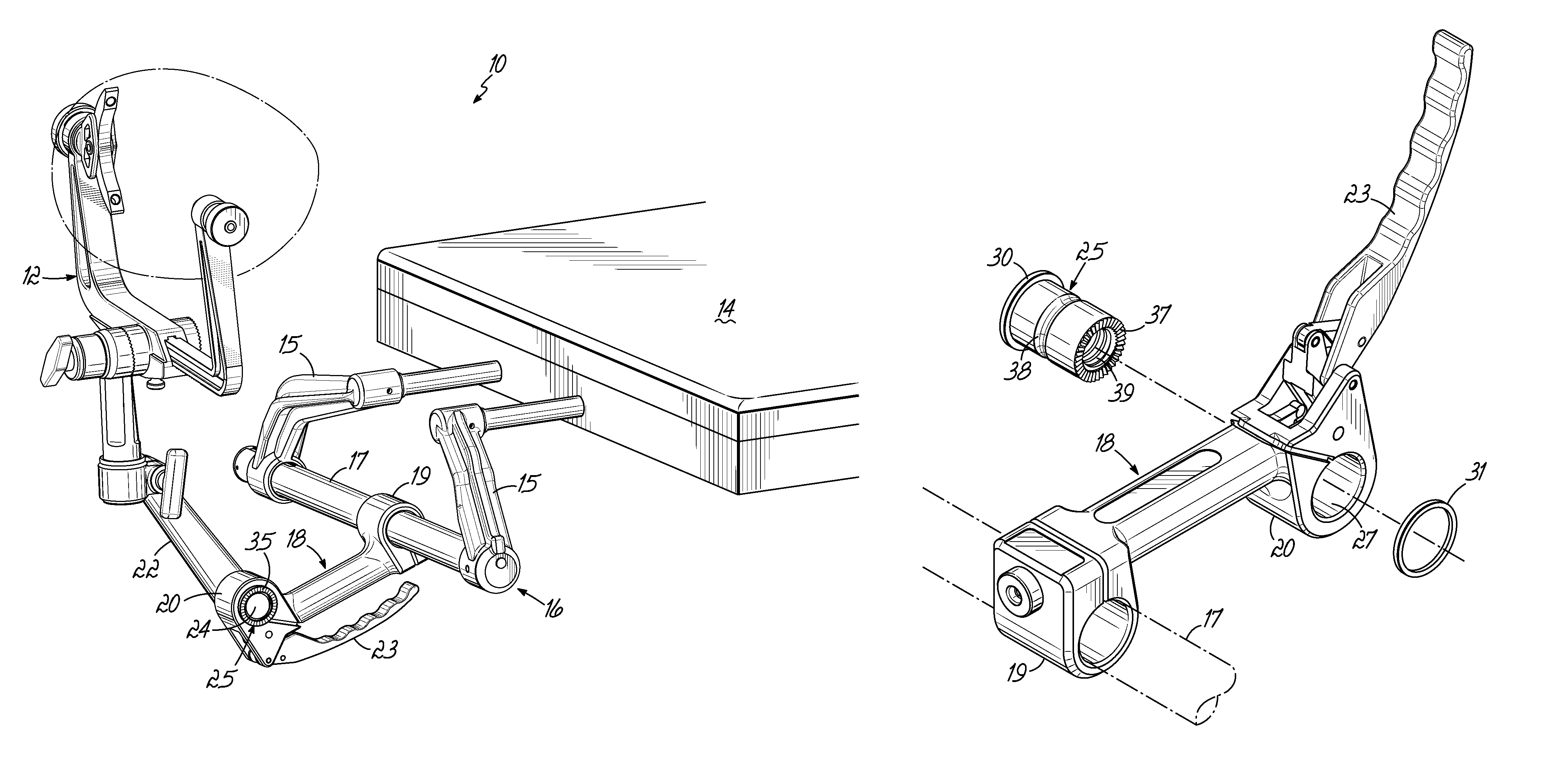
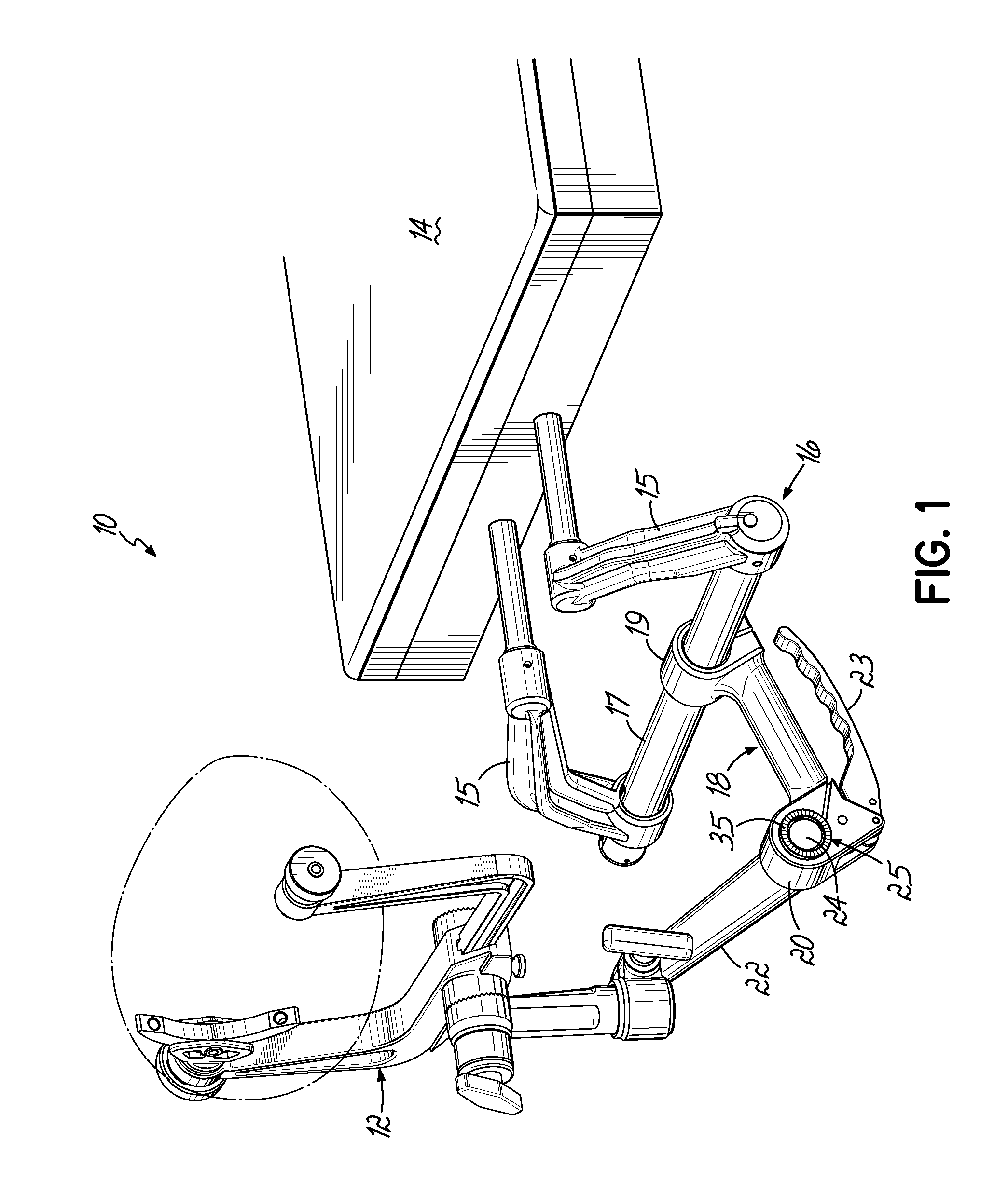
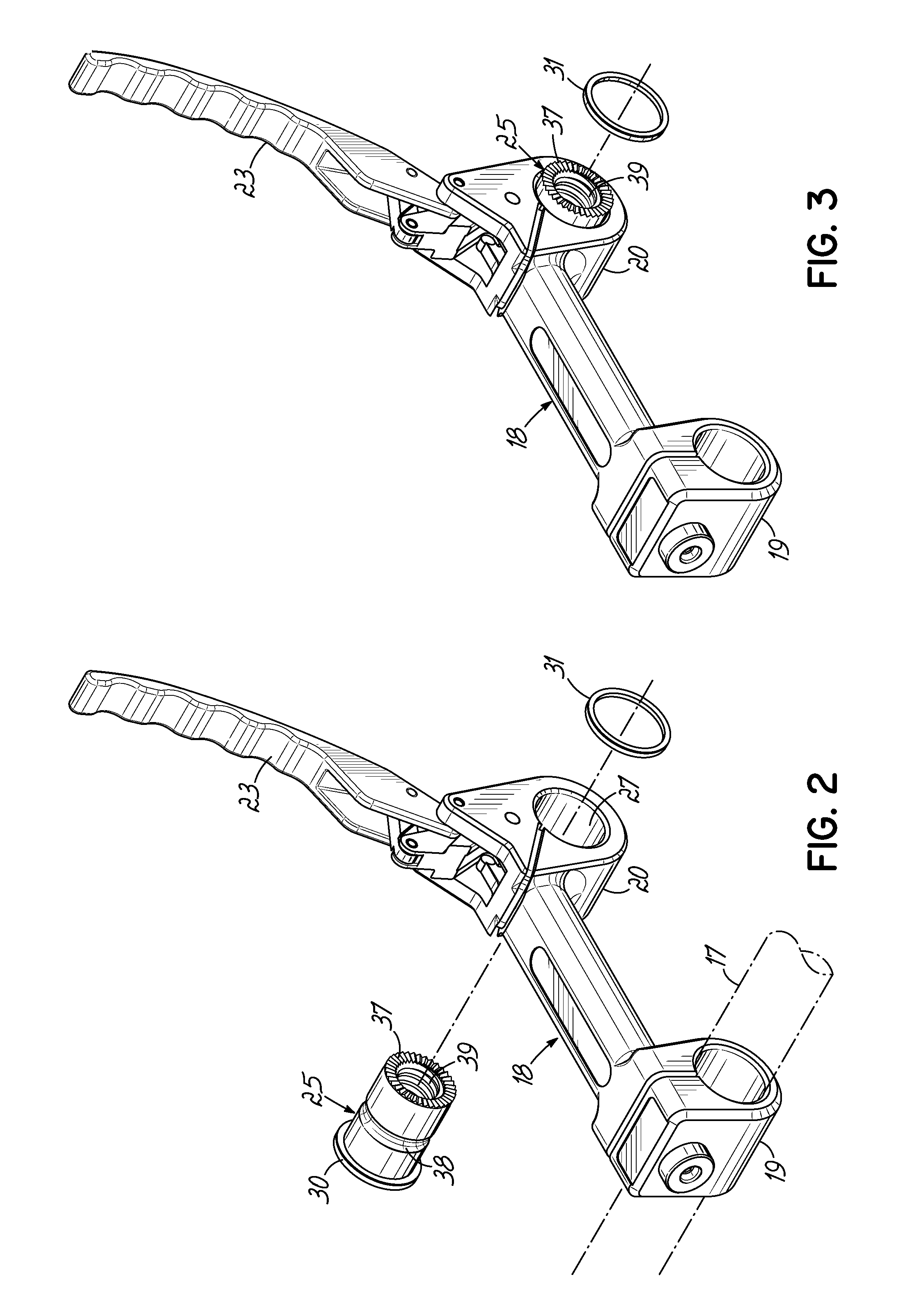
[0032]FIG. 1 shows a head support system 10 for supporting a patient (head shown in phantom) via a skull clamp 12 at the end of a surgical table 14. According to the arrangement of components shown in FIG. 1, in addition to the skull clamp 12, the head support system 10 includes a base unit 16, which includes a crossbar 17 that spans between a pair of spaced connector legs 15, and a base unit handle 18. The legs 15 connect to the table 14 and support the crossbar 17. The base unit handle 18 has a first end 19 that connects to the crossbar 17 and a second end 20 that connects to a transition member 22. The transition member 22 operatively connects the skull clamp 12 to the base unit 16. In this example, the transition member 22 serves as an intervening member. Those skilled in the art will readily appreciate that one or more adaptors or transition members could be used as the intervening member, or members, for interconnecting the base unit 16 and the skull clamp 12.

[0033]The focus o...


PUM


Abstract

A patient head support system comprises a base unit, a head support, and an intervening member for connecting the base unit and the head support. The base unit includes a handle assembly with an elongated body, a bore at one end thereof, and a lever that moves relative to the body between closed and open positions to contract and to expand the bore, respectively. A sleeve retained within the bore is sized to receive and hold a shaft of the intervening member, so as to hold the intervening member in a fixed position when the lever is closed. The sleeve remains retained in the bore when the transition member is disconnected, to resist contracting of the bore caused by inadvertent closing of the lever when the intervening member is unattached, and to protect against the unwanted intrusion of material into the bore.

Description

RELATED APPLICATION[0001]The present application claims priority to U.S. Ser. No. 61 / 475,795 filed Apr. 15, 2011, the disclosure of which is incorporated herein by reference in its entirety.FIELD OF THE INVENTION[0002]The present invention relates to a patient head support system suitable for use during neurosurgery, and more particularly, to an improvement related to connecting the base unit handle to another component.BACKGROUND OF THE INVENTION[0003]Patient head support systems for securing the head of a patient during surgical or radiological procedures are known in the art. Such head support systems typically include a base unit that connects to a patient table, a skull clamp or headrest that holds a patient's head, and intervening structure for interconnecting the base unit to the skull clamp or headrest. These components, namely, the base unit, the intervening structure, and the skull clamp or headrest, adjust so the head of the patient may be secured in any one of a number o...

Claims


Application Information

Patent Timeline
Patent Type & Authority Patents(United States)
IPC IPC(8): A61G13/12A47C20/00
CPCA61G13/121A61G13/101
Inventor ROLFES, SEAN
Owner INTEGRA LIFESCI
Why Eureka
Try Eureka