
Humidity sensor based on progressive corrosion of exposed material

a technology of humidity sensor and exposed material, applied in the field of electronic circuits, can solve the problems of material to thin, metal surface continues to thin until nothing remains, corrosion is dependent on moisture content, etc., and achieves the effect of ensuring the flawless operation of the integrated circuit and relatively easy control of general corrosion

Inactive Publication Date: 2014-04-01
AMS INT
View PDF17 Cites 20 Cited by
  • Summary
  • Abstract
  • Description
  • Claims
  • Application Information

AI Technical Summary

Benefits of technology

The patent text describes a new sensor that takes a different approach to humidity sensors. It uses the corrosion characteristics of a material to track the humidity content of the atmosphere. The sensor is made using standard semiconductor technology processes, which ensures accuracy and reliability. The sensor has no hysteresis, meaning it is not affected by previous humidity levels and can provide accurate readings. The technical effect of this new sensor is that it provides a more reliable and accurate means to control humidity in the manufacturing process of integrated circuits, ensuring their optimal functioning.

Problems solved by technology

It damages the entire surface of the material at about the same rate, causing the material to thin.
However, if not controlled, the metal surface continues to thin until nothing is left.
Indeed, corrosion is dependent on moisture content.

Method used


Image

  • Humidity sensor based on progressive corrosion of exposed material
  • Humidity sensor based on progressive corrosion of exposed material
  • Humidity sensor based on progressive corrosion of exposed material

Examples


Embodiment Construction

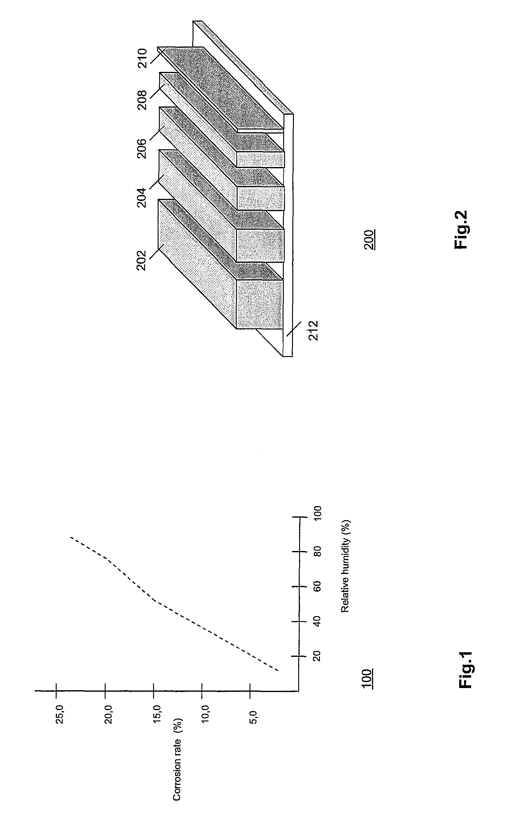
[0028]FIG. 1 is a diagram 100 showing the relationship between corrosion rate (in percentages) and relative humidity (in percentages), measured for a temperature between, say, 20°-30° C. The diagram is based on the publication of Lin and Zhang mentioned above. The dependence is roughly linear over the range of relative humidity.

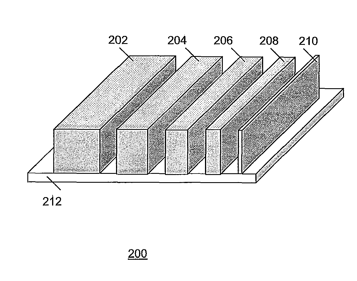
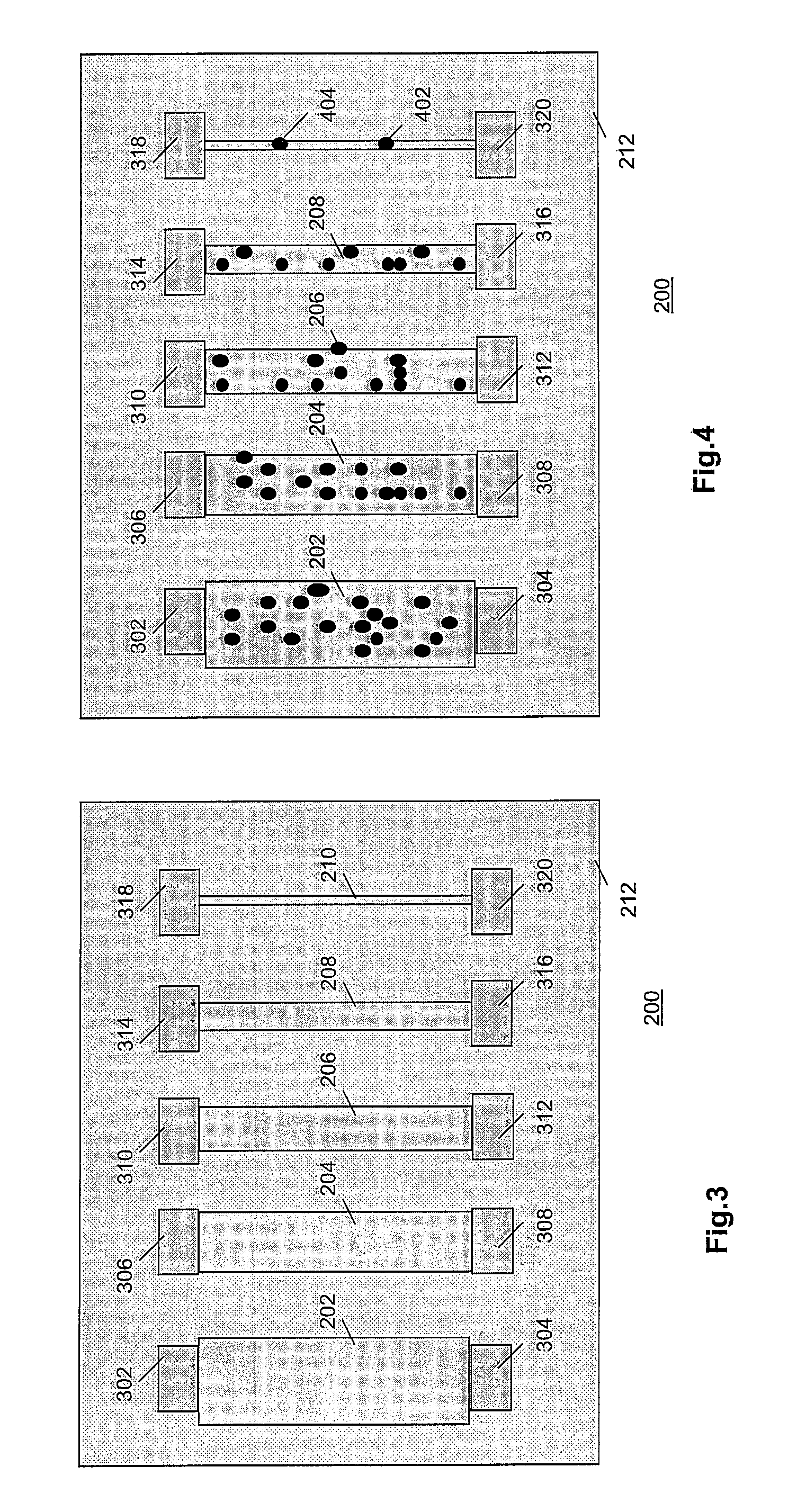
[0029]FIG. 2 is a diagram of an array 200 of differently sized strips 202, 204, 206, 208 and 210 of a material sensitive to corrosion for use in a humidity sensor according to the invention. Strips 202-210 are formed on a substrate 212. Typically, array 200 is manufactured in a semiconductor process, e.g., CMOS, using lithographic exposure and dry-etching, on substrate of a semiconductor material, e.g., silicon. The material that forms strips 202-210 comprises, e.g., a metal that is conventionally deposited in such a process to form interconnects. Preferably, the spaces between strips 202-210 are filled with another material (not shown) that is much less sens...


PUM

PropertyMeasurementUnit
corrosive-sensitiveaaaaaaaaaa
impedanceaaaaaaaaaa
corrosiveaaaaaaaaaa

Abstract

A sensor senses a characteristic of an environment, e.g., humidity. The sensor has a substrate with strips of material that is sensitive to corrosion as a result of the characteristic. The strips are configured to respond differently to the characteristic. By means of repeatedly measuring the resistances of the strips, the environment can be monitored in terms of accumulated exposure to the characteristic. The strips are manufactured in a semiconductor technology so as to generate accurate sensors that behave predictably.

Description

FIELD OF THE INVENTION[0001]The invention relates to an electronic circuit comprising a sensor to sense a characteristic, e.g., humidity or contamination (e.g., dust or a specific chemical compound such as ammonia), of the environment of the sensor, and to a method of sensing this characteristic.BACKGROUND ART[0002]Humidity sensing is of great importance in many industrial applications, including monitoring of pharmaceutical, biomedical, food / beverage storage and logistics, electronics, automotive and semiconductors industries. For the food monitoring application for example, measuring the relative humidity inside the package is necessary to monitor the quality of the product, as excessive moisture content may lead to premature spoilage. In such application, the miniaturization of the sensors is also a key element.[0003]The vast majority of the humidity sensors nowadays commercially available are capacitive sensors. Such sensors use a material, whose dielectric constant change as a ...

Claims


Application Information

Patent Timeline
Patent Type & Authority Patents(United States)
IPC IPC(8): G01N19/00
CPCG01N17/04
Inventor HUMBERT, AURELIEPONOMAREV, YOURI VICTOROVITCHMERZ, MATTHIASHOOFMAN, ROMANO
Owner AMS INT
Learn More