Compact binocular adaptive optics phoropter

a binocular adaptive optics and phoropter technology, applied in the field of binocular vision and eye treatment, can solve the problems of patients with less than ideal vision, uncorrected vision degrade, and patients with less than ideal correction in at least some instances

Active Publication Date: 2014-04-01
AMO DEVMENT
View PDF11 Cites 21 Cited by
  • Summary
  • Abstract
  • Description
  • Claims
  • Application Information

AI Technical Summary

Benefits of technology

[0016]In many embodiments, the optical path extends between the first mirror and the second mirror and a majority of the optical path extends transverse to the line of sight so as to decrease a separation distance between the first mirror and the second mirror, such that the line of sight is substantially maintained when the person views the target with light reflected from the first mirror.
[0030]In many embodiments, the optical path between the first mirror and the second mirror extends a first cumulative distance along a first direction transverse to the optical axis of the eye. The optical path extends between the first mirror and the second mirror a second cumulative distance along a section direction corresponding the optical axis of the eye. The first cumulative distance is greater than the second cumulative distance so as to decrease a separation distance between the first mirror and the second mirror.
[0036]In many embodiments, the at least one lens comprises one lens having a cross sectional size corresponding to a size of the first lens combined with a size of the second lens. The optical path extends from the first lens to a first portion of the one lens and the optical path extends from the second lens to a second portion of the one lens. The first portion of the one lens is located away from a center of the one lens opposite the first lens to deflect the optical path toward the deformable mirror with prism of the one lens. The second portion of the one lens is located away from the center opposite the second lens and opposite the first portion to deflect the optical path toward the mirror with prism of the one lens such that the optical path from the first lens to the first portion crosses the optical path from the second lens to the second portion. This crossing of the optical path can decrease substantially a dimension of the apparatus transverse to the line of sight and can also produce images of the viewing target as seen by the patient that are upright, non-inverted, and not flipped, such that the person can perceive the viewing target with correct orientation.
[0043]In many embodiments, a sensor is configured to measure a position of the pupil, and the sensor and the deformable mirror are coupled to circuitry to adjust a profile of the deformable mirror based on the position of the pupil. Alternatively or in combination, the second mirror may comprise an adjustable mirror coupled to the sensor so as to adjust the second mirror based on the position of the pupil such that location of the image of the pupil on the deformable is substantially maintained when the pupil moves.

Problems solved by technology

However, the eye can have defects that may result in less than ideal vision in at least some instances.
For example, refractive errors of the eye can cause uncorrected vision to degrade.
Correction of the refractive error of the eye with spherical and cylindrical lenses may not fully correct at least some of the optical errors of the eye and can leave a patient with less than ideal correction in at least some instances.
For example, the eye can have aberrations such as spherical aberration and coma that limit the effectiveness the refractive prescription that may be used with treatments such as spectacles and contact lenses.
Also, although optical instruments such as microscopes, cameras, binoculars, telescopes and long range sighting (hereinafter “LRS”) may correct for at least some optical errors of eye such as sphere, uncorrected spherical aberration and coma can limit vision with such optical instruments in at least some instances.
Although the human eye can perceive colors such as the primary colors red, blue and green, the human eye has chromatic aberration such that vision can be degraded when more than one color is viewed.
However, at least some vision correction treatments such as refractive surgery, contact lenses, and intraocular lenses (hereinafter “IOLs”) can induce high order aberrations of the eye.
For example, the pupil may be larger than the proposed optical correction at night with some patients, such that at least some aberrations may result with night vision following treatment.
At least some of the prior devices used to measure and test vision with aberrations prior to treatment such as surgery can perform less than ideally in at least some instances.
For example, at least some of the prior devices that measure and correct monochromatic aberrations are not well suited for the evaluation of vision with polychromatic light.
As normal vision can include polychromatic light, testing vision with monochromatic light may not provide a realistic assessment of vision with polychromatic light in at least some instances.
Also, at least some of the prior devices determine vision with monocular viewing, and normal vision can be binocular such that testing a proposed treatment with monocular vision can be less than ideal.
Although some of the prior systems have tested binocular vision with aberration correction, these systems have produced less than ideal results in at least some instances.
For example, at least some of the prior systems have relied on the patient viewing a target inside the apparatus in an artificial viewing environment that may not accurately assess vision.
Also people can often be aware of their surroundings, and viewing an artificial target positioned inside the apparatus may result in the patient perceiving that he or she is looking inside the apparatus rather than at a remote target, such that the measurements can be less than ideal in at least some instances.
Also, at least some of the prior binocular viewing systems may have flat target and in at least some instances may not present a three dimensional viewing environment for the patient to test vision as would occur normal vision in a room.

Method used


Image

  • Compact binocular adaptive optics phoropter
  • Compact binocular adaptive optics phoropter
  • Compact binocular adaptive optics phoropter

Examples


Embodiment Construction

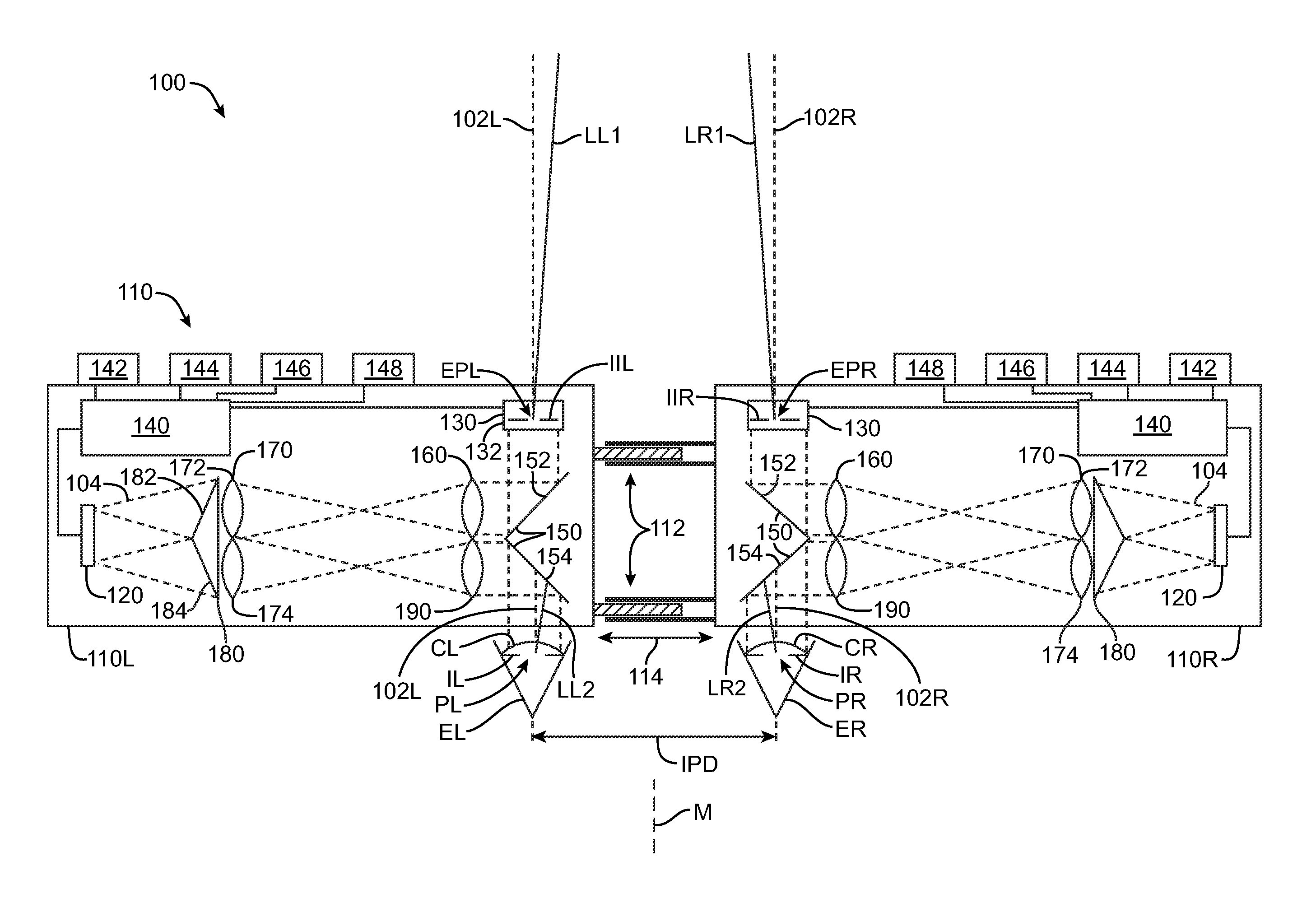
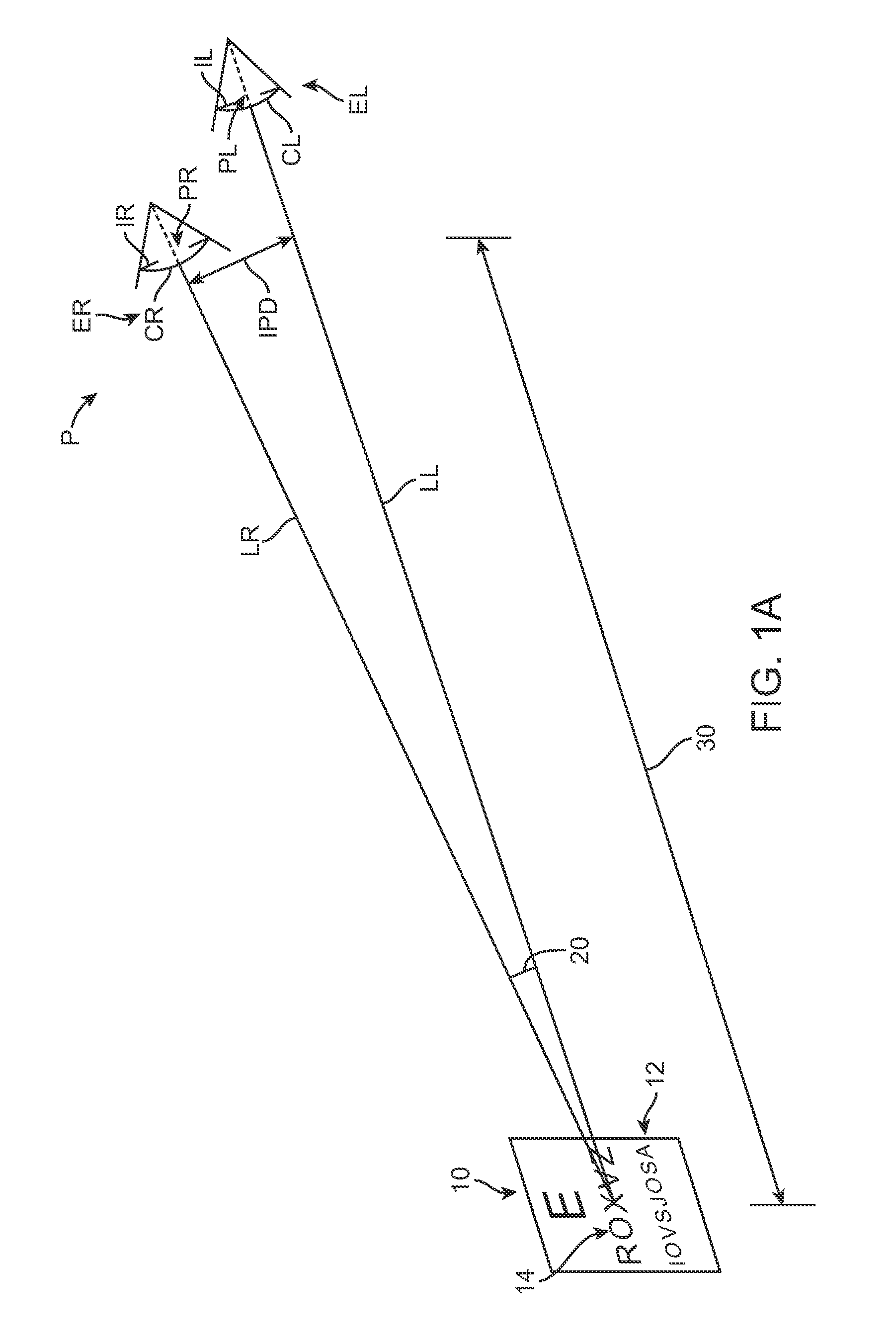
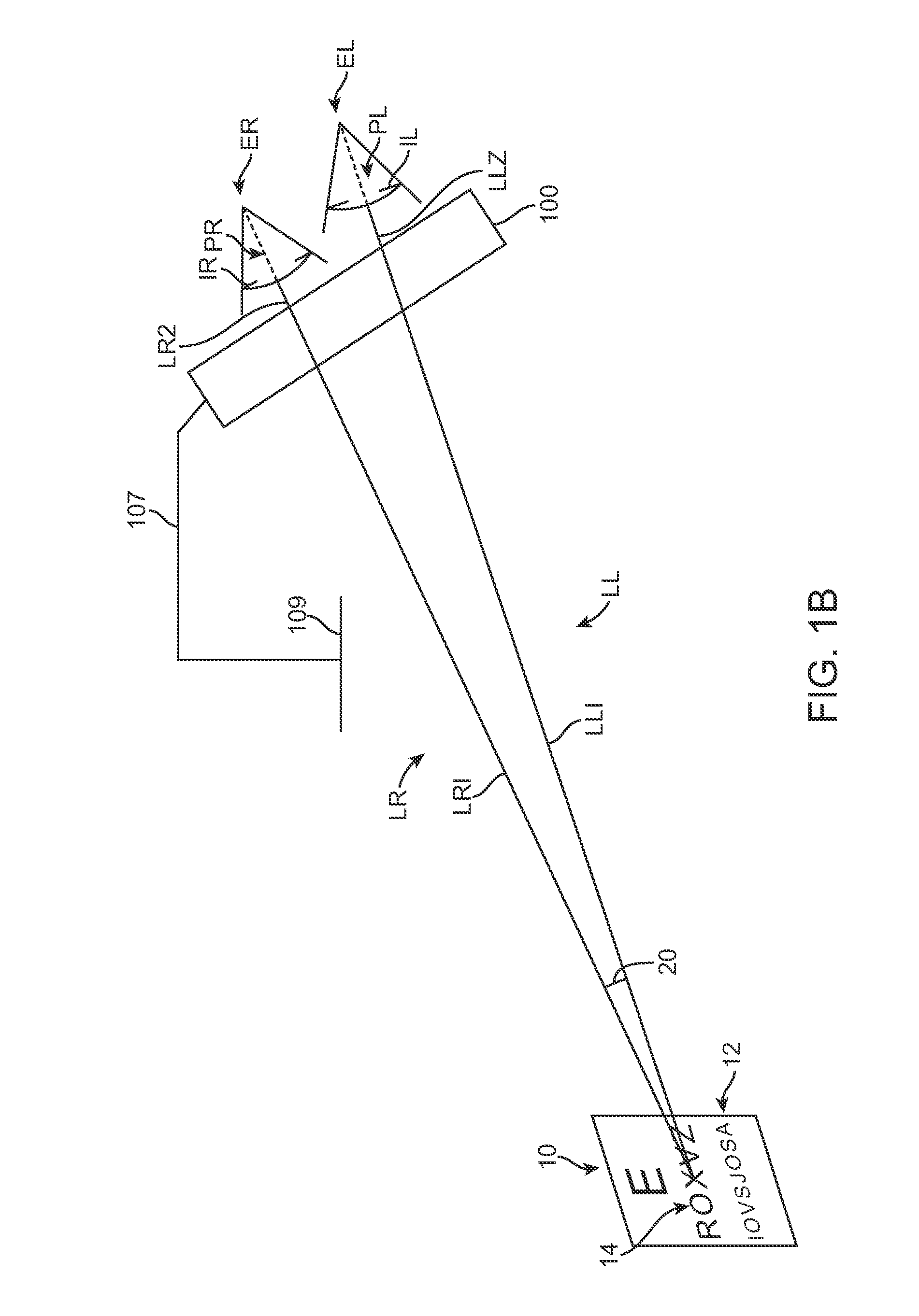
[0055]Embodiments of the present invention are well suited for providing binocular vision with aberration adjustment, for example partial or full correction, such that the vision of the eyes can be tested in a normal viewing environment such as a room. The embodiments as described herein can be used to evaluate many forms of vision correction such as refractive surgery, contacts, spectacles, orthokeratology, IOLs and LRS designs, for example. Evaluation of binocular vision with adjustment to an amount of aberration can be helpful to determine diagnosis and treatment, and the embodiments as described herein allow the health care provider such as an optometrist, an ophthalmologist, a certified ophthalmic technician, or an optician to adjust the aberrations provided to the patient so as to test different amounts of aberration with binocular vision such that the patient and health care provider can evaluate aberration correction prior to treatment in a natural viewing environment. For e...


PUM


Abstract

A binocular vision apparatus allows a patient to view objects through the apparatus with polychromatic light and monochromatic aberration correction, such that the chromatic aberration of the eye can be combined with the monochromatic aberration correction, so as to provide a more accurate determination of vision quality. The binocular vision apparatus provides left and right viewing optics that can substantially maintain the line of sight of each eye, such that objects can be viewed in a room with 3D depth perception corresponding to the distance of the object from the patient. As both near and far objects can be viewed with binocular aberration correction, the patient can alternate binocular viewing between near and far vision with chromatic aberration so as to evaluate a proposed treatment such as a presbyopia correction.

Description

CROSS-REFERENCES TO RELATED APPLICATIONS[0001]Not ApplicableSTATEMENT AS TO RIGHTS TO INVENTIONS MADE UNDER FEDERALLY SPONSORED RESEARCH AND DEVELOPMENT[0002]Not ApplicableBACKGROUND OF THE INVENTION[0003]The present invention is related to binocular vision and treatment of the eye.[0004]People like to see. However, the eye can have defects that may result in less than ideal vision in at least some instances. For example, refractive errors of the eye can cause uncorrected vision to degrade. Refractive errors of the eye include nearsightedness, also referred to as myopia, farsightedness, also referred to as hyperopia, and astigmatism. These refractive errors can be treated with combinations of spherical lenses and cylindrical lenses, and the refractive prescription used to treat an eye, sometimes referred to as a refraction, can include a spherical optical power, a cylinder optical power and an axis of the cylinder. An example of a prior device that can be used to test vision with sp...

Claims


Application Information

Patent Timeline
Patent Type & Authority Patents(United States)
IPC IPC(8): A61B3/032A61B3/10A61B3/08A61B3/02
CPCG02B13/22G02B27/0025A61B3/036A61B3/032A61B3/103G02B3/0087A61B3/1015A61B3/10A61B3/08A61B3/02A61B3/111
Inventor NEAL, DANIEL, R.
Owner AMO DEVMENT
Why Eureka
Try Eureka