Power supply and DC-DC-conversion

a power supply and converter technology, applied in pulse manipulation, pulse technique, instruments, etc., can solve problems such as difficulty in processing feedback signals

Active Publication Date: 2014-04-01
NXP BV
View PDF5 Cites 2 Cited by
  • Summary
  • Abstract
  • Description
  • Claims
  • Application Information

AI Technical Summary

Benefits of technology

[0005]In accordance with one or more of the embodiments a fast adding circuit for combining a current feedback signal and an oscillator signal in a DC / DC converter is provided which does not cause additional delay.

Problems solved by technology

Further, with increasing switching frequency of a DC / DC converter of e.g. 6 MHz, it is difficult to process feedback signals such as adding two signals with adequate current consumption and no extra signal delay.

Method used


Image

  • Power supply and DC-DC-conversion
  • Power supply and DC-DC-conversion
  • Power supply and DC-DC-conversion

Examples


Embodiment Construction

[0028]These and other aspects of the invention will be apparent from and elucidated with reference to the embodiment(s) described hereinafter and illustrated in the drawings.

[0029]The present invention is further elucidated by the following figures and examples, which are not intended to limit the scope of the invention. The person skilled in the art will understand that various embodiments may be combined.

BRIEF DESCRIPTION OF THE DRAWINGS

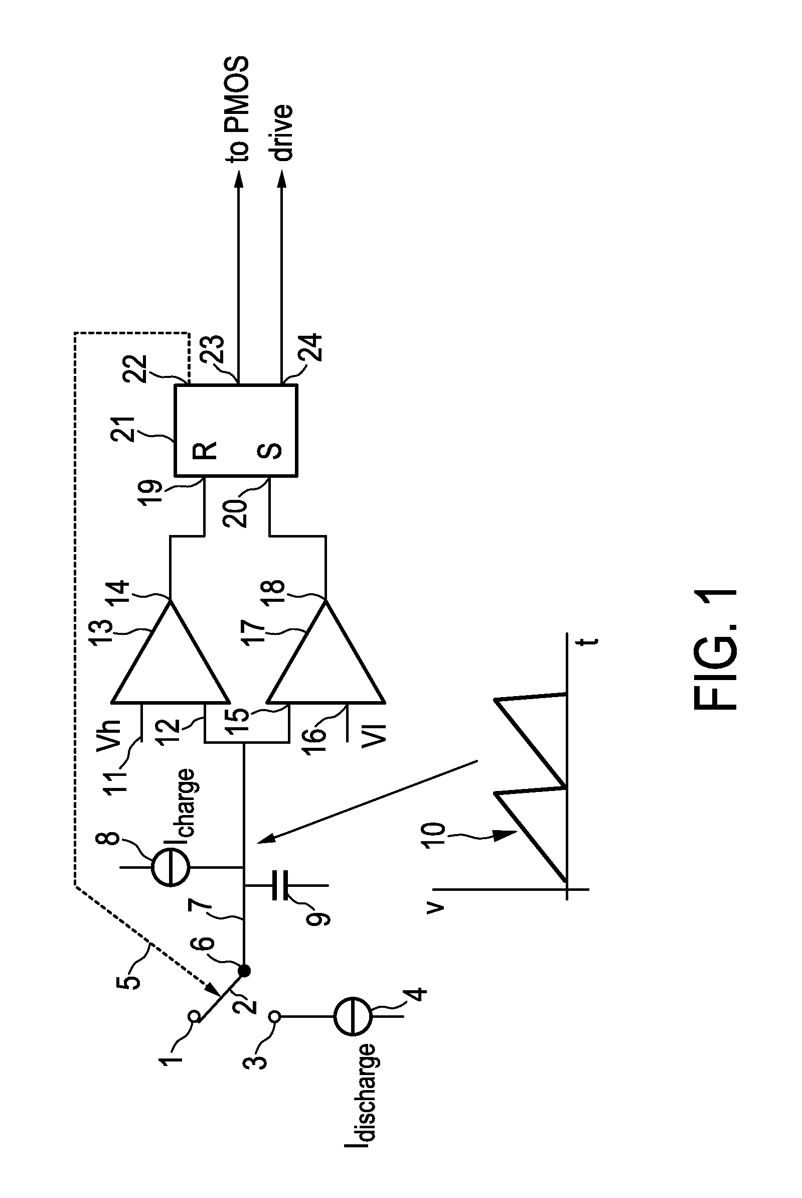
[0030]FIG. 1 shows a basic diagram illustrating an example embodiment of a pulse-width-modulated signal generating circuit in accordance with an exemplary implementation the invention,

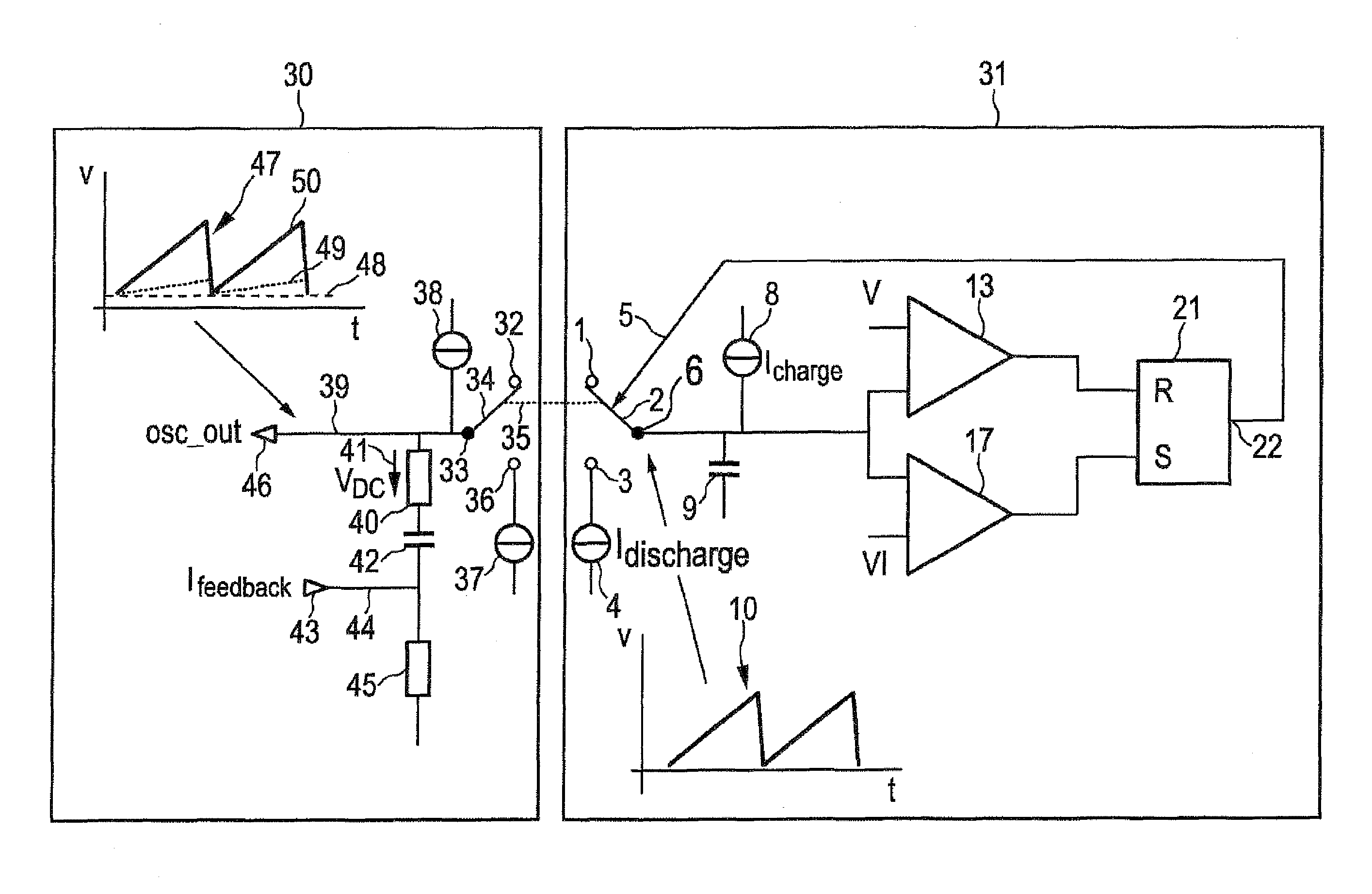
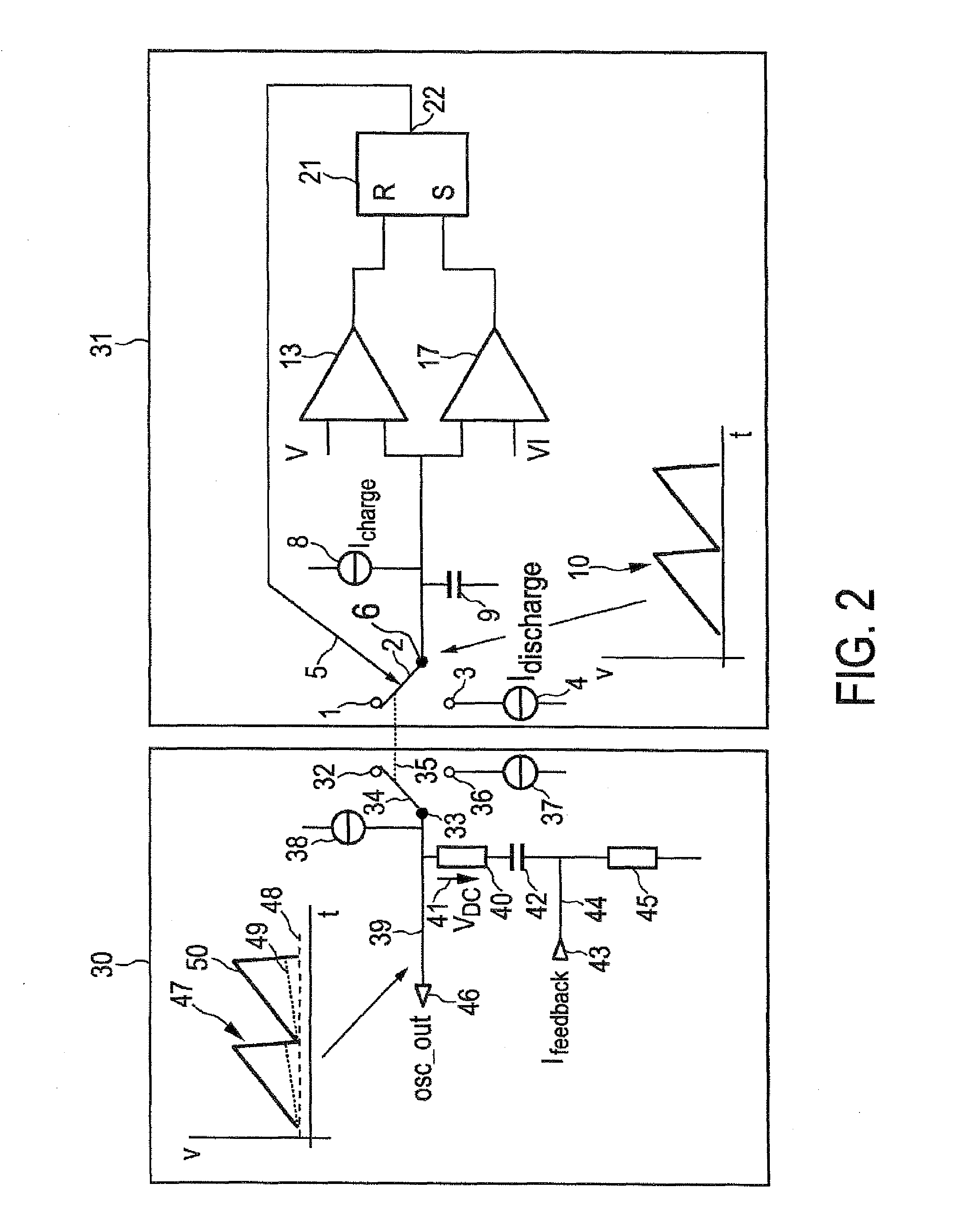
[0031]FIG. 2 schematically shows an example of an implementation of a primary oscillator and a replica oscillator in accordance with an exemplary implementation of the invention, and

[0032]FIG. 3 shows an embodiment of an example configuration of a dc-to-dc converter in accordance with an embodiment in line with the invention.

DETAILED DESCRIPTION OF EMBODIMENTS

[0033]FI...


PUM


Abstract

In an embodiment of a converter, a first oscillator provides switching signals for switching between charging and discharging of a capacitor, and a second oscillator is configured to add an offset voltage or a feedback-current-dependent voltage to a sawtooth waveform generated by the second oscillator switched in synchronism with the first oscillator.

Description

[0001]This application claims the priority under 35 U.S.C. §119 of European patent application no. 09168891.1, filed on Aug. 28, 2009 the contents of which are incorporated by reference herein.FIELD OF THE INVENTION[0002]At least one or more embodiments generally relate to sawtooth waveform generation, an oscillator, a power supply and DC-DC (DC=direct current or voltage, unipolar current or voltage) conversion.BACKGROUND OF THE INVENTION[0003]U.S. Pat. No. 7,215,104 describes an DC / DC converter which is configured to provide a desired output setting voltage at a load-side output. The DC-DC converter comprises an oscillator outputting an oscillation clock to a slope circuit. The slope circuit generates a sawtooth waveform voltage having a slope which begins at the leading edge of the oscillation clock. A comparator compares the sawtooth waveform voltage and an output voltage of an error amplifier. A logic circuit is set by the trailing edge of the oscillation clock, and is reset by ...

Claims


Application Information

Patent Timeline
Patent Type & Authority Patents(United States)
IPC IPC(8): H03K3/26
CPCH03K4/502H02M3/156
Inventor BEIER, RALFOSTERLOH, GERHARDGATTUNG, MICHAEL
Owner NXP BV
Why Eureka
Try Eureka