Leak detection method and system for a high pressure automotive fuel tank

a detection method and high-pressure technology, applied in the direction of instruments, fluid-tightness measurement, combustion-air/fuel-air treatment, etc., can solve the problem of pressure being bled-o

Inactive Publication Date: 2014-04-08
CONTINENTAL AUTOMOTIVE SYST INC
View PDF12 Cites 10 Cited by
  • Summary
  • Abstract
  • Description
  • Claims
  • Application Information

AI Technical Summary

Problems solved by technology

These systems, however require pressure to be bled-off before tank diagnostics can be run.

Method used


Image

  • Leak detection method and system for a high pressure automotive fuel tank
  • Leak detection method and system for a high pressure automotive fuel tank
  • Leak detection method and system for a high pressure automotive fuel tank

Examples


Embodiment Construction

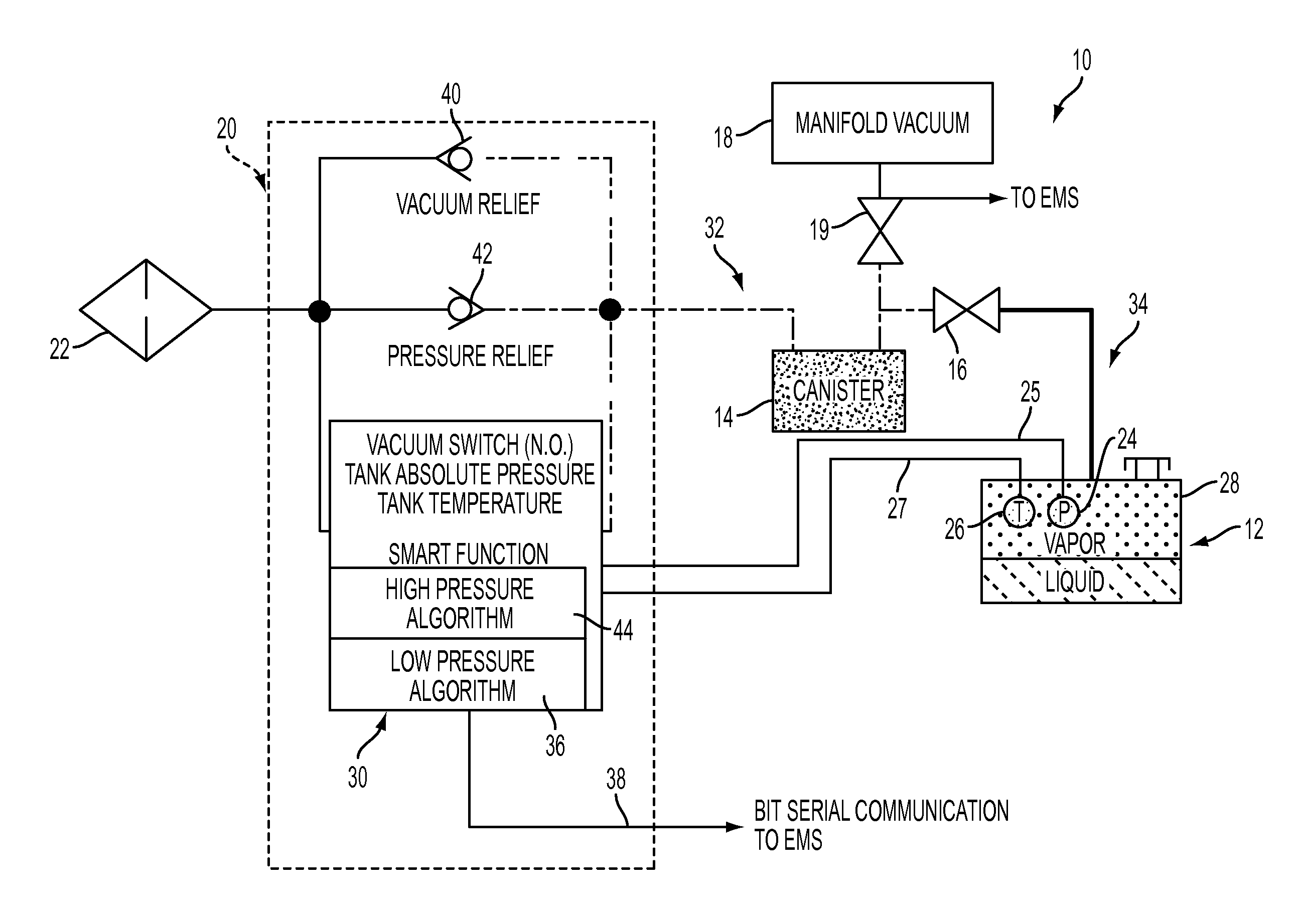
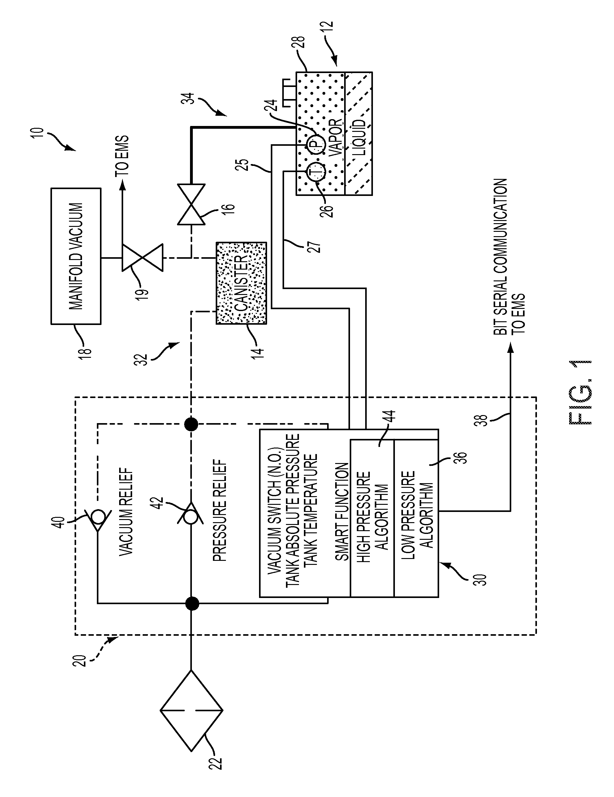
[0014]Referring to FIG. 1, a diagnostic vapor management system for a high pressure fuel tank is shown, generally indicated at 10, in accordance with an embodiment. The high pressure (sometimes called “non-integrated”) system 10 comprises of a fuel tank, generally indicated at 12, a charcoal, vapor collection canister 14, a tank pressure control valve 16 between the canister 14 and tank 12, vacuum source 18, such as an intake manifold of the engine, a purge valve 19 between the canister 14 and vacuum source 18, a leak detection valve, generally indicated at 20, and a filter 22. An absolute pressure sensor 24 and a temperature sensor 26 are located within the vapor cavity 28 of the fuel tank 12. In the embodiment, the pressure sensor 24 and temperature sensor 26 are electrically connected to a processor, generally indicated at 30, within the leak detection valve 20. If desired, the processor 30 can be provided remote from the leak detection valve 20.

[0015]It is understood that volati...


PUM


Abstract

A vapor management system (10) includes a fuel tank (12), a canister (14), a pressure control valve (16) between the tank and canister and defining a high pressure side (34) and a low pressure side (32), a vacuum source (18), a purge valve (19) between the canister and vacuum source, a leak detection valve (20) connected with the canister and including a processor (30). A pressure sensor (24) and a temperature sensor (26) are disposed in a fuel vapor cavity of the fuel tank, with signals from the sensors being received by the processor. Based on an absolute temperature measured by the temperature sensor, the processor compares a predicted pressure in the fuel tank to the measured absolute pressure, and identifies a leak on the high pressure side if the predicted pressure is outside a tolerance range, while maintaining pressure in the fuel tank.

Description

FIELD OF THE INVENTION[0001]This invention relates to vapor management systems of vehicles and, more particularly, to a leak detection method and system for high pressure automotive fuel tank.BACKGROUND OF THE INVENTION[0002]A known fuel system for vehicles with internal combustion engines includes a canister that accumulates fuel vapor from a headspace of a fuel tank. If there is a leak in the fuel tank, the canister, or any other component of the fuel system, fuel vapor could escape through the leak and be released into the atmosphere instead of being accumulated in the canister. Various government regulatory agencies, e.g., the U.S. Environmental Protection Agency and the Air Resources Board of the California Environmental Protection Agency, have promulgated standards related to limiting fuel vapor releases into the atmosphere. Thus, there is a need to avoid releasing fuel vapors into the atmosphere, and to provide an apparatus and a method for performing a leak diagnostic, so as...

Claims


Application Information

Patent Timeline
Patent Type & Authority Patents(United States)
IPC IPC(8): F02M33/02G01F17/00G01M3/00G01M15/00G01M3/04
CPCF02M25/0809
Inventor PERRY, PAUL, D.
Owner CONTINENTAL AUTOMOTIVE SYST INC
Why Eureka
Try Eureka