Rack type pipe feeder for a pipe fusion machine

a fusion machine and pipe feeder technology, applied in the direction of de-stacking articles, manufacturing tools, transportation and packaging, etc., can solve the problems of increasing the downtime of the fusion machine, the inability of fork trucks to reposition the pipe stick longitudinally, and the inability to effectively manipulate the pipe stick into the fusion machine. , to achieve the effect of reducing the impact force of the discharged stick

Active Publication Date: 2014-04-08
MCELROY MFG
View PDF50 Cites 14 Cited by
  • Summary
  • Abstract
  • Description
  • Claims
  • Application Information

AI Technical Summary

Benefits of technology

[0025]Use of the racks, dispensers and stands allows a plurality of sticks to be stored on a racks at one time, releasing the heavy lifting equipment and its operator to work elsewhere. The fusion process will require only one operator and the pipe sticks are handled by heavy equipment only once, when delivered pipe is lifted from the truck and placed on the racks. The dispensers load one stick at a time from the racks to the stands by use of gravitational force while retaining the remaining sticks of pipe on the inclined rack. Both the tracked and roller pipe stands are self-powered to align pipe sticks vertically and laterally with the fusion machine. The drive assembly stand can axially drive the pipe in the stands while t

Problems solved by technology

Handling and staging sticks of pipe to be fed into a pipe fusion machine are presently labor intensive, time consuming tasks requiring use of expensive pipe loading, unloading and manipulating equipment and causing extensive downtime of the fusion machine while each stick of pipe is maneuvered into the machine and of the peripheral equipment while the fusion machine is in operation.
Some pipe stands are available for use in the pipe fusion process, but they hold only one stick of pipe at a time and, despite use of the stand, other jobsite equipment is still required to load and position each and every stick of pipe in the fusion machine.
It is not, however, an effective tool for manipulating sticks of pipe into a fusion machine.
Furthermore, because of the pipe size, terrain contour and pipe loading limitations of this combination, there are many applications in which it is of little use at all.
A fork truck cannot be used to reposition the stick of pipe longitudinally.
The person per

Method used


Image

  • Rack type pipe feeder for a pipe fusion machine
  • Rack type pipe feeder for a pipe fusion machine
  • Rack type pipe feeder for a pipe fusion machine

Examples


hydraulic embodiment

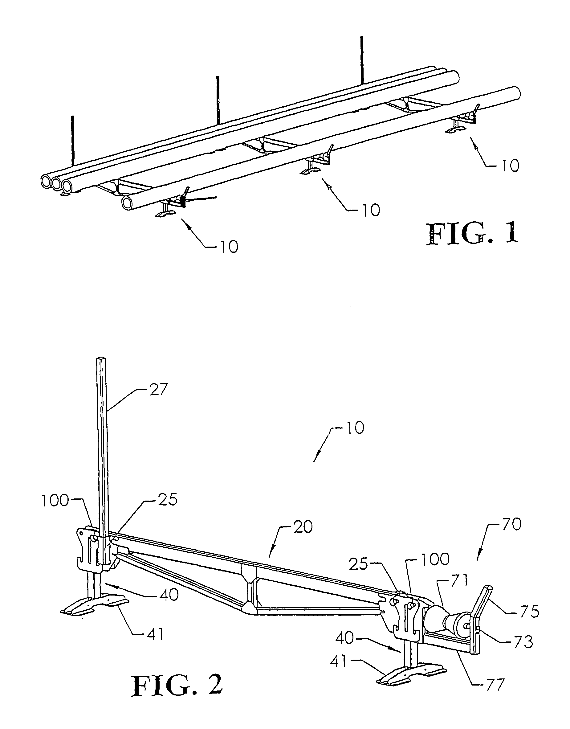
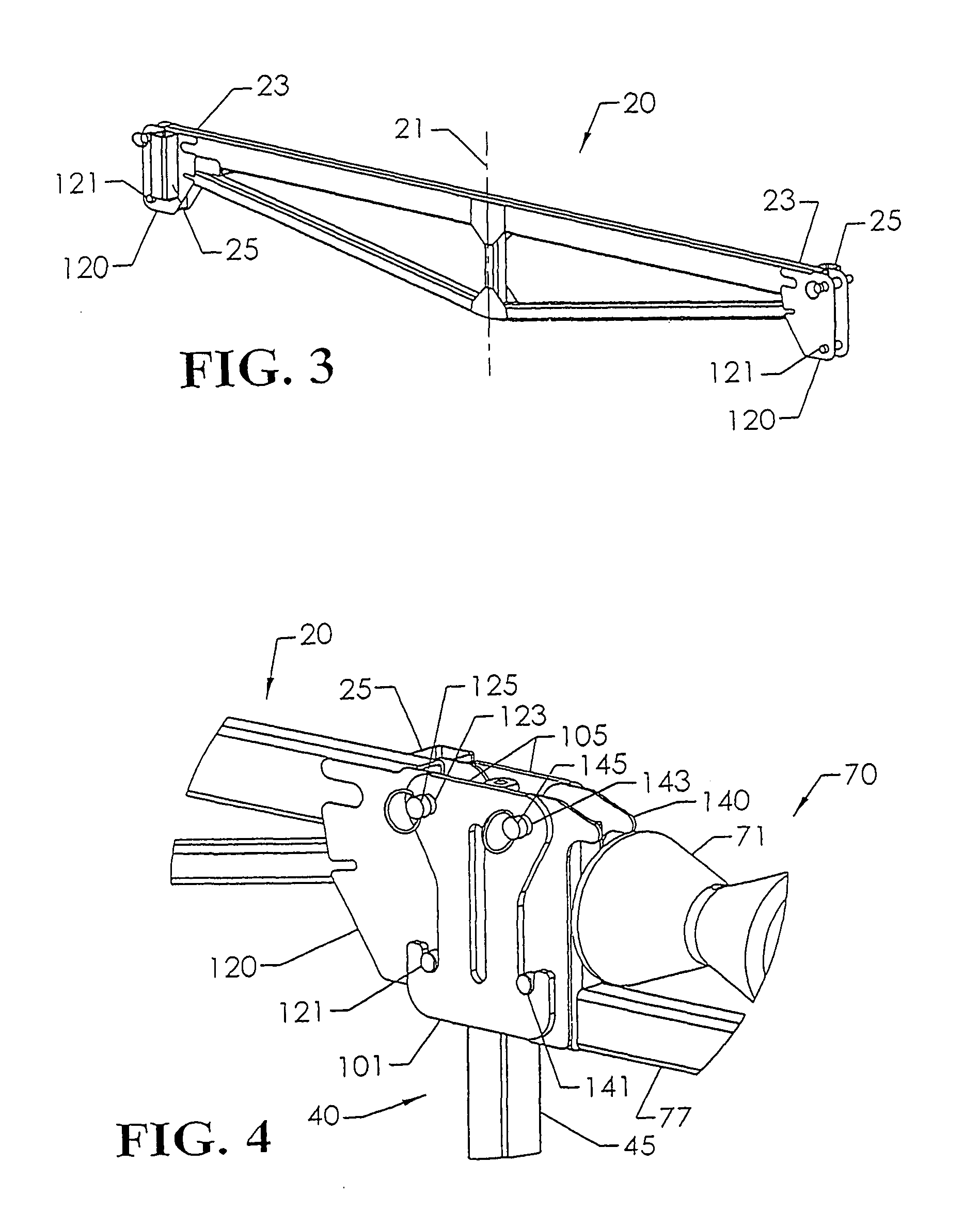
[0071]Turning to FIGS. 8A, 8B and 8C, a hydraulic embodiment of a front leg 200 and roller assembly 220 of the pipe rack is illustrated.

[0072]The leg 200 supports the beam 20 above the ground. It has a foot 201 and an upright 203. Preferably, and as shown, the upright 203 supports a telescoping tubular extension 205 which can be manually raised and lowered to adjust the height of the leg 200. The leg 200 can be locked at a selected height by insertion of a pin 207 into aligned apertures 209 in the upright 203 and telescoping extension 205 when the desired height is set. A clevis 211 is welded to a lower portion of the telescoping extension 205 to support a clevis pin 213. A horizontal L-shaped frame 215 of tubular members is welded at one end to and extends away from the telescoping extension 205 at a point above the clevis 211. The frame 215 extends from the telescoping extension 205 in a direction parallel to the clevis pin 213 and then turns in the same direction as the clevis 21...


PUM

PropertyMeasurementUnit
Forceaaaaaaaaaa

Abstract

For use in loading heavy sticks of plastic pipe into a pipe fusion machine, a pipe storage rack with hydraulically powered pipe stick dispensers and stands allows sticks of pipe stored on the rack to roll gravitationally onto a rocking V-shaped dispenser cam disposed between the rack and the fusion machine loading path for one-stick-at-a-time loading onto powered track and roller stands which enable Cartesian manipulation of the stick into the fusion machine. The cam is adjustable to suit pipe stick diameters ranging from 20″ to 48″. Many sticks can be stored at one time, releasing heavy lifting equipment and operators to work elsewhere. The process requires only one operator using a pendant controller and the pipe sticks are handled by heavy equipment only when being loaded onto the racks.

Description

PRIORITY CLAIM[0001]This application is a continuation-in-part (CIP) of U.S. patent application Ser. No. 12 / 283,391 (CIP) filed Sep. 11, 2008 entitled RACK TYPE FEEDER FOR A PIPE FUSION MACHINE which claimed priority to U.S. patent application Ser. No. 11 / 518,052 (Parent) filed Sep. 8, 2006 entitled RACK TYPE PIPE FEEDER FOR A PIPE FUSION MACHINE. This application also claims priority to U.S. Provisional Patent Application No. 61 / 371,329, filed Aug. 6, 2010.BACKGROUND OF THE INVENTION[0002]This invention relates generally to high density polyethylene (HDPE) pipe fusion equipment and more particularly concerns equipment for feeding sticks of pipe into a machine for fusion to the trailing end of a pipeline.[0003]Handling and staging sticks of pipe to be fed into a pipe fusion machine are presently labor intensive, time consuming tasks requiring use of expensive pipe loading, unloading and manipulating equipment and causing extensive downtime of the fusion machine while each stick of p...

Claims


Application Information

Patent Timeline
IPC IPC(8): B65G47/08B65G65/34B65G65/44B65G59/06B28B21/90
CPCB29C31/002B65G1/0442B29C66/65B65G65/34B28B21/90B65G59/06B65G47/08B65G65/44B29C65/78B29C66/5221B29C66/71B29K2023/00B65G47/06B65G1/08B29K2023/065
Inventor PERRAULT, JAMES R.PORTER, DAVID WARRENJACKMAN, BRANDON WILLIAMDRAEGER, WILLIAM BARTONMURRAY, BOBBY L.THOMAN, TIMOTHY M.MCELROY, II, ARTHUR H.
Owner MCELROY MFG
Why Eureka
Try Eureka